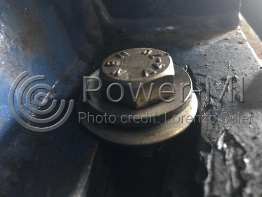
The mismatch is the condition in which elements that must interact with each other for their correct operation lose their property or exceed their tolerance range to exercise their joint function correctly. Normally the mismatch refers to mechanical tolerances, however, there are cases in which it can be applied to process parameters that must maintain a relationship.

Causes
The most common causes of visual inspection detectable mismatch are:
- Bad assembly or changes in operating conditions.
- Thermal expansion.
- Movements of benches or foundation concrete.
- Structural changes.
- Change of parts or elements.
- Imprecision in machining.
- Vibrations.
- Material wear.
Cases
Through visual inspections, the most common cases of misadjustment that are diagnosed are:
- Gear tooth clearance or play.
- Bearings.
- Shaft couplings.
- Pulleys.
- Shaft keyway.
- Clear between flat mechanical joints.
- Warping of machine benches.
- Straightness and parallelism of rails.
- Lack of flatness or unevenness of floors, benches, and foundations.
Diagnosis
The detection of the mismatch in visual inspections is by linear measurement with a Vernier or caliper gauge or micrometer, checking with shims or with the use of levels, ropes, or laser.
Points to consider:
- The diagnosis of misadjustment in visual inspections is not through specialized instrumentation (theodolites, laser equipment) that require installation and commissioning. If measuring with precision instruments, it is best to do so outside of the visual inspection routes.
- Shaft misalignment, flatness, straightness, and parallelism can be diagnosed as misalignments on visual inspections. However, it is recommended to check for misalignment using specific measurements and specialized instruments.

 cloud_download