Vibration Analysis of Centrifugal Fans

Fans is a type of machinery that is present in almost any type of industry. Moreover, they are used daily in domestic ventilation or air conditioning applications. In many industrial systems and processes, these machines are critical assets that deserve special attention, starting with the specialized monitoring of their dynamic and operational condition.
Fans are essential for the current industry, and we could say that they play a relevant role in how modern society works. Their fundamental application is transporting or driving air, gases or vapors in ventilation systems, heat exchange systems or processes involving gas combustion. But, the flow of air can also be used as a mean of transport for other products, such as powders or small solids, a typical use in industries like the food and the cement industry, for example.
In general, industrial fans are classified in two big groups: centrifugal fans and axial fans. Each of them with specific mechanical and operational characteristics, in addition to failure modes which are very specific to each group. In this article, we will focus on the monitoring and analysis of problems found in centrifugal fans.
A centrifugal fan is a relatively simple machine. However, they can develop mechanical and operational failures that require the analysis of different parameters such as gas flow, working speed, load, level of noise, temperature and vibrations levels, just to mention some of the most relevant variables.
What is a centrifugal fan?
Generally, a fan is a machine that produces gas flow by creating a pressure differential through the exchange of momentum of the vanes of the fan with the gas particles. The impeller of the fan transforms the rotating mechanical energy in kinetic energy inside the gaseous fluid. This energy is partially transformed into static pressure later. In a centrifugal fan, the fluid enters in the direction of the length of the rotating shaft, and it is discharged perpendicular or radially, so the fluid experiments a change in direction of 90°. Figure 1 shows the direction of the fluid.

-
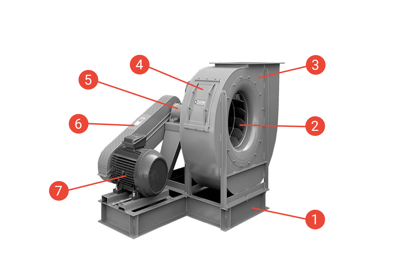
Foundation or structural support: it may share the structure with the conductor or it may have an independent foundation. The foundation can be flexible if the natural frequency is lower than the working RPM, or rigid foundation when the natural frequency is higher than the working RPM of the fan.
-
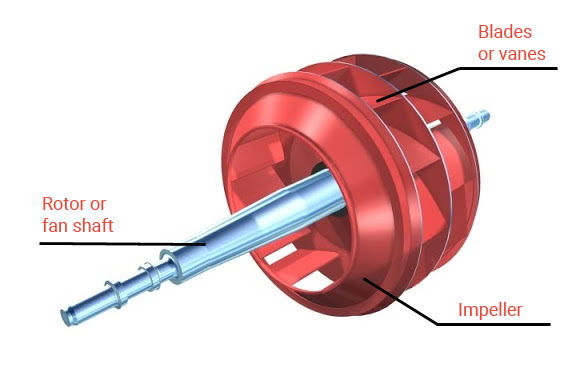
Impeller and vanes: the impeller or wheel is coupled to the rotor or the shaft of the fan. It is formed by a series of blades or vanes which are shaped depending on the type of fan and its application or operational requirement. Figure 3 shows an impeller and its vanes.
-
Volute or casing: it is the container of the fluid, where the energy exchange between the impeller and the fluid takes place. From this point, the fluid is directed from the suction to the discharge.
-
Access door: for the inspection of the equipment in maintenance situations.
-
Rolling bearings or flat bearings: depending on the size of the equipment, its weight and working speed, they can be provided with rolling bearings or flat bearings. Some applications with flat bearings also have refrigeration systems for the lubricant.
-
Transmission system: there are several configurations available depending on the design. The pulley and belt transmission system is one of the most common and reliable ones. However, it is limited to a certain speed range. When the speed of the fan exceeds 3000 RPM, a direct transmission system is typically used, which can be by couplings between the drive and the fan or simply installing the impeller directly on the motor shaft.
-
Driving equipment: According to the operational characteristics and other factors, the driving equipment can be an AC motor, a DC motor or even steam turbines. Read also our article Vibration Analysis of Electric Induction Motors.
Vibration Measuring Points
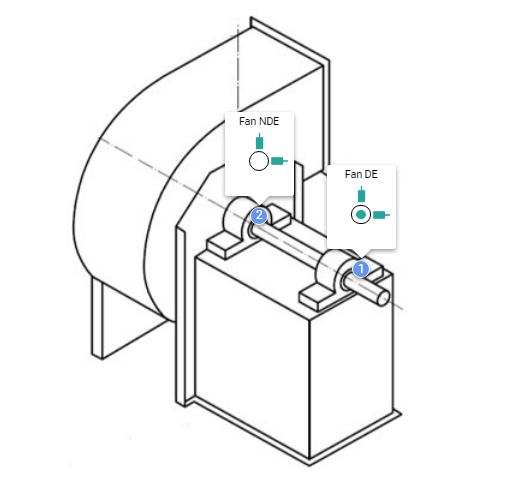
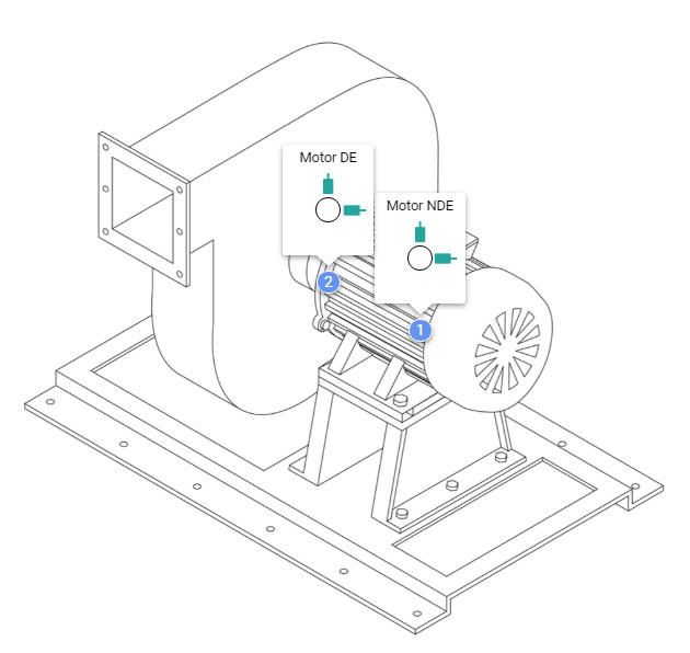
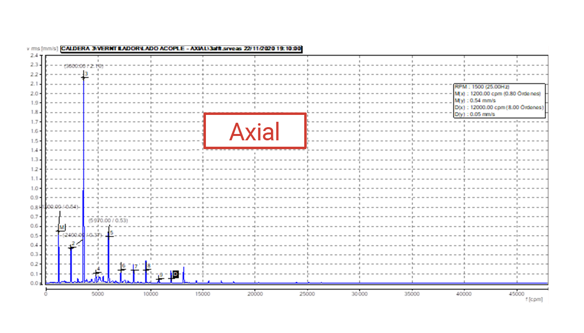
As we have discussed in a general way in our article Where to place the vibration sensor in a centrifugal fan, measures must be taken on all its flat and rolling bearings, provided that it is safe, take measures in the horizontal (H), vertical (V) and axial (A) directions of each rotor support. Figure 4 shows the measuring location of a cantilever fan supported on roller bearings. Figure 5 shows a configuration with the rotor directly installed on the motor. In this case, vibration monitoring is restricted to the measures taken on the motor.
Safety is a priority when selecting the vibration monitoring points.
Failures in centrifugal fans which can be detected by vibration analysis
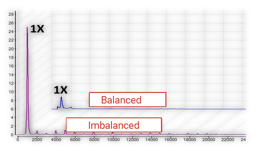
 Imbalance
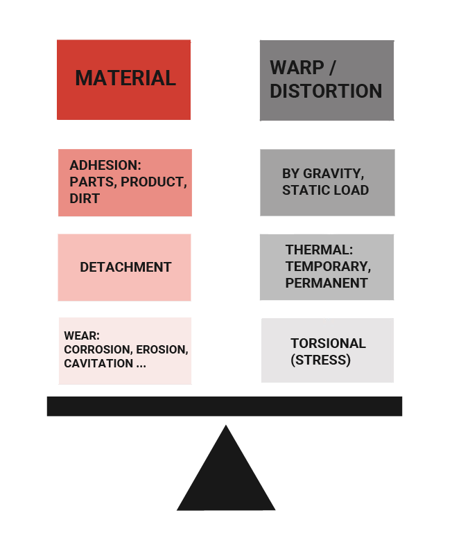
In centrifugal fans, imbalance is one of the most common failures, and it usually happens due to one of the following causes:
- Thermal deformation: This can happen because of a thermal shock during operation, but it can also happen when a hot rotor is left out of service for a period long enough to allow gravity and its own weight to create the deformation.
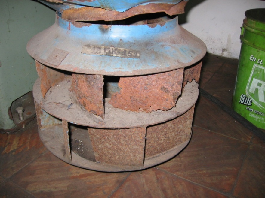
- Material loss due to wear erosion, corrosion. Figure 6 shows an impeller with a high level of corrosion.
- Adherence of particles or dirt to the impeller / rotor.
- Surface treatments or painting work.
- Deformation due to torque or overload.
- Inadequate balancing procedure in the workshop.
When imbalance is detected in centrifugal fans, the following actions could be recommended:
- Checking the operation and maintenance log to verify when the problem appeared: during operation, after maintenance, new motor, etc. This will help with the root cause analysis.
- Assessing the integral dynamic condition of the drive-fan group to evaluate collateral damage on flat bearings/roller bearings, belts, couplings, foundation and structure.
- Adequately analyzing the problem to define the corrective procedure according to the dynamic of the type of imbalance found (dynamic, couple, static), as well as the balancing method (1 plane, 2 planes, multi-plane) and whether balancing at the shop or on-site is required.
- Planning the precision balancing action according to the applicable standards: API, ISO 21940/11, ISO 21940/12, ISO 14694.
 Misalignment
In centrifugal fans, another very common failure is misalignment, which usually happens due to one of the following causes:
- Inadequate procedure by the maintenance personnel.
- Inadequate application of the alignment standards and tolerances.
- Thermal expansión.
- Weakness or deficiency of the supporting foundation.
- Uneven leg or distortion of the motor foundation.
- Coupling failure, excessive runout or wear.
- Wear or damage of pulleys/belts.
When misalignment is detected in centrifugal fans, the following actions could be recommended:
- Assessing the procedures and capabilities of the personnel.
- Practicar la alineación de precisión aplicando los estándares pertinentes: Performing precisión alignment under the corresponding standards: API 686, ANSI/ASA 2,75
- Measuring and correcting the distortions of uneven leg. (in the drive and the driven equipment)
- Assessing the integrity of the foundation and the coupling.
- Assessing the impact of the thermal expansion and considering it in the procedure of alignment.
 Bent shaft
In centrifugal fans, the bent shaft usually happens due to one of the following causes:
- Deformation due to gravity when the rotor stays static for long periods. It can basically occur in long shutdown periods in heavy equipment, more than 1,000 Kg.
- Deformation during operation due to thermal shock, overload, or excessive torque.
When the bent shaft is detected in centrifugal fans, the following actions could be recommended:
- Activating a root cause analysis process to determine the failure mechanism.
- Measuring the runout in the shaft and impeller to confirm the problem.
- It is possible for a bent fan to be balanced and, this way, the vibrational effect may be corrected, but this is generally a temporary solution, since the rotor might go back to its original shape while in operation.
- Special procedures may be required to revert the deformation.
 Structural issues
In centrifugal fans, structural issues usually happen due to one of the following causes:
- Weakness of the foundations due to corrosion or any other physicochemical attack.
- Terrain movement.
- Foundation resonance with any of the operating frequencies of the system.
- Damaged, isolated or loose bolts.
- Wrong foundation design.
When structural issues are detected in centrifugal fans, the following actions could be recommended:
- Assessing the integrity and general condition of the foundations, both for the machine and for the supporting structure, including the ducts of the system.
- Assessing the condition of the fixing bolts.
- Tightening the bolts to the specified torque.
- Verifying the natural frequency and possible resonance.
 Rub
Rub
In centrifugal fans, the rub usually happens due to one of the following causes:
- Wrong assembly, inadequate or defective parts.
- Inadequate clearance between static and rotating parts.
- Excessive imbalance or misalignment.
- Distortion due to ducts tension.
When rub is detected in centrifugal fans, the following actions could be recommended:
- Verifying the assembly procedures, clearances and the quality of the parts.
- Assessing the presence of other failure such as imbalance, misalignment or resonance.
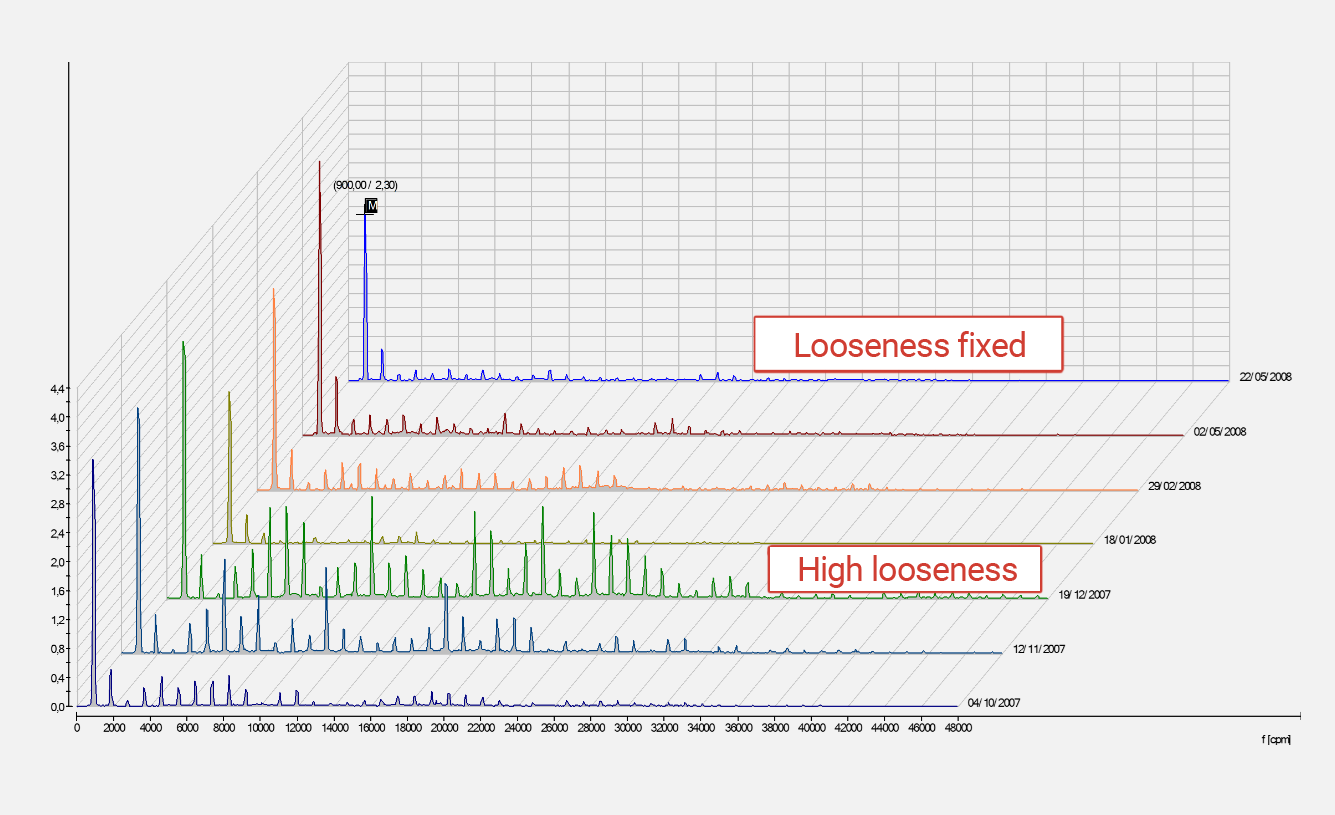
 Rotating looseness
In centrifugal fans, rotating looseness usually happens due to one of the following causes:
- Roller / flat bearings wear.
- Wear of the roller / flat bearing housing.
- Bad quality of lubrication, either excess or lack of it.
- Wrong assembly of parts such as rolling bearings, flat bearings, couplings, pulleys.
- Defective or inadequate parts.
When rotating looseness is detected in centrifugal fans, the following actions could be recommended:
- Verifying the assembly procedures, clearances and the quality of the parts.
- Auditing the lubrication process.
- Replacing parts which are in bad conditions, deteriorated or inadequate.
 Bearing issues
In centrifugal fans, bearing issues usually happen due to one of the following causes:
- Lubrication failures.
- Wrong assembly of components.
- Bad quality or deteriorated parts.
- Collateral damage from excessive misalignment or imbalance.
- Life span wear.
When a bearing issue is detected in a centrifugal fan, the following actions could be recommended:
- Analyzing the root cause of the failure and correct it, so the action is not only taken on the symptom.
- Auditing the assembly and lubrication processes.
- Replacing affected components.
More about the failure analysis in bearings can be read in Typical bearing defects and spectral identification.
 Flow issues
In centrifugal fans, a flow issue usually happens due to one of the following causes:
- Failures in the flow entry and flow discharge control systems.
- Operational changes such as the operating speed.
- Changes in the conditions of the fluid: density, temperature, etc.
- Problems in the suction filters.
When flow issues are detected in a centrifugal fan, the following actions could be recommended:
- Verifying the control system and the load, RPM and flow relation.
- Assessing the changes in the operational conditions or the characteristics of the fluid.
- Perform an extensive dynamic analysis to evaluate collateral damage.
- Verifying the integrity of the duct system and how it adapts to the design.
- Cleaning the filters and other obstructions.
 Resonance
In centrifugal fans, resonance usually happens due to one of the following causes:
- Working RPM close to the natural frequency of the foundation and other parts of the system.
- Structural weakening that changes the rigidity of the supports.
- Influence of external machinery on the natural frequency of the system.
- Changes in the operational conditions: Variable RPM.
When resonance is detected in a centrifugal fan, the following actions could be recommended:
- Performing an impact test in the high vibration zones to determine the natural frequency and compare them with the operating frequencies or those of the surroundings of the machine.
- Performing a Bode analysis to find critical speeds.
- Assessing the integrity of the foundation and the general structure to find any possible weakening or rigidity changes.
 Lubrication issues
In centrifugal fans, a lubrication issue usually happens due to one of the following causes:
- Lubrication issues considerably affect the roller / flat bearings of the system.
- Lubrication failures may happen due to an excessive amount of lubricant, bad quality lubricant, lack of refrigeration or poor heat dissipation, very low amount and/or frequency of lubrication, lubricant contaminated with humidity or solid particles.
When lubrication issues are detected in a centrifugal fan, the following actions could be recommended:
- Root cause analysis. Assessing the lubrication procedures, the capabilities of the personnel, the quality and cleanliness of the lubricant.
- Do not confuse the symptoms (bearing damage) with the cause of the failure, replacing the bearings is only an effect, correcting the problem means performing a technical and cultural process to implement a proactive and precise culture about the integral process of lubrication.
Other predictive technologies
Centrifugal fans inspection, as well as the inspection of any other rotating equipment, must be integral, including the dynamic, thermal, and operational behavior. The following technologies also apply for monitoring centrifugal fans:
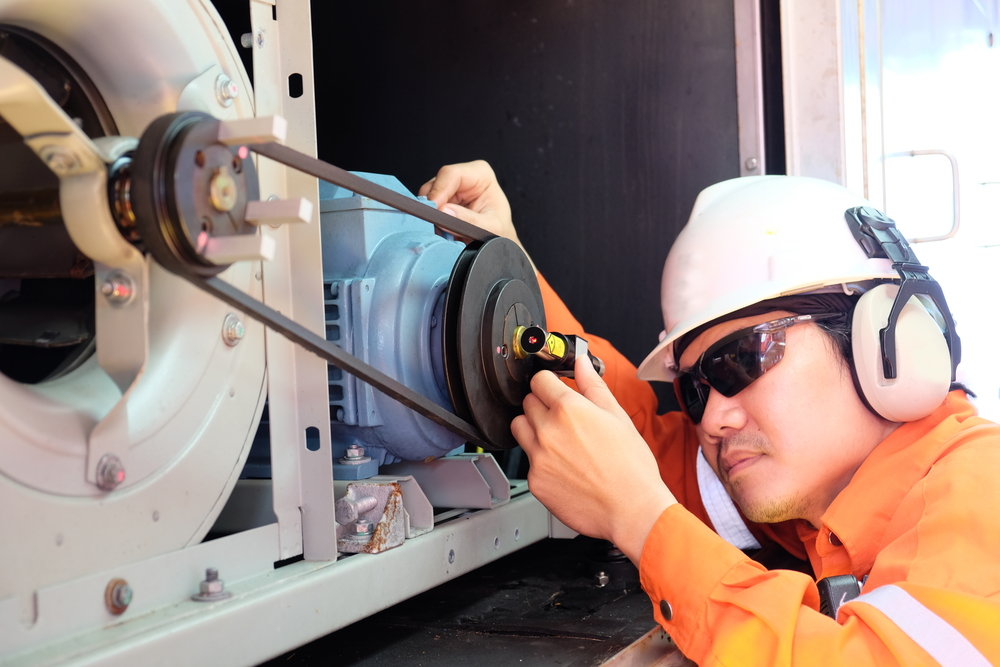
 Visual inspection: it is the first line of defense of monitoring, all the inspection programs must include integral observation routines to verify loose parts, unsafe conditions, abnormal audible noise, cleanliness and neatness of the area, leaks, corrosion, painting, etc.
 Ultrasound: it is a very effective technique for monitoring bearings, even at an earlier stage than conventional vibration, monitoring the ultrasonic noise is also a tool to perform lubrication in an optimal way.
 Oil analysis: evaluating the physicochemical properties and cleanliness of the lubricant must be a standard activity of any integral inspection program. Many centrifugal fans have central lubrication systems, the health of these systems is critical for the reliable and safe operation of the rotating equipment.
 Infrared thermography: monitoring some modes of failure associated to temperature increments may complement the vibration analysis. Assessing the thermal profile of the bearings always considering that the ultrasonic noise and vibration are earlier symptoms than the temperature increment. Assessing the parts of the refrigeration systems such as radiators, heat dissipators, refrigerant and lubricant reservoirs. In any equipment driven by electric motors, it is always recommended to perform the thermography monitoring on the power and control systems.
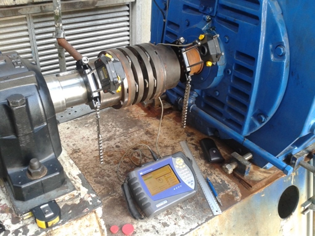
 Alignment measuring: by using laser technology, controlling misalignment is much easier, accurate and above all faster nowadays, which allows to include this inspection technique as part as the proactive routines that try to battle stress, excessive friction, heat, vibration and excessive energy consumption.
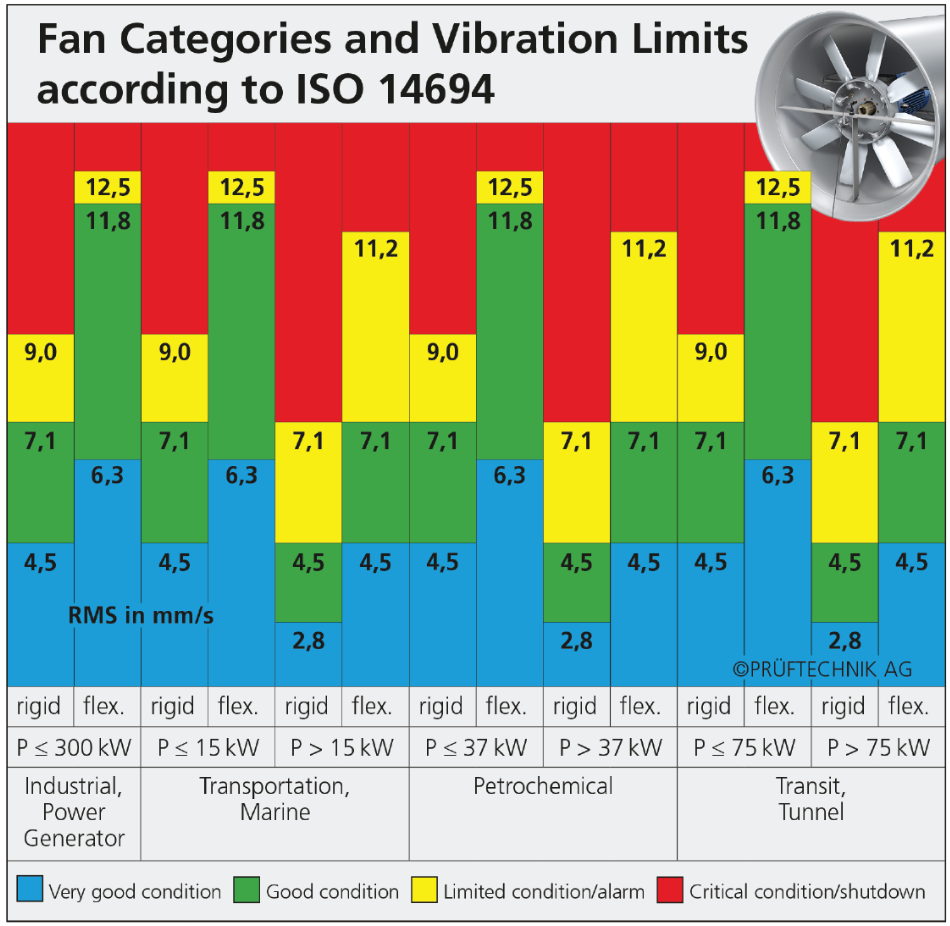
Norms and standards
The permissible vibration limits for these machines can be found in some recognized standards. Among them, the standard ISO 14694 establishes the guidelines for permissible vibration levels and permissible imbalance specifically for industrial centrifugal fans in several categories and applications. The ANSI/ASA S2,75 norm establishes the guidelines for the precision alignment, a frequent activity performed on these machines, both in those using direct coupling and those with belts/pulleys systems.
Conclusions
Centrifugal fans are an essential part of the industrial processes in the modern industry. This is why it is important to establish inspection programs based on the characteristic failure mode analysis, the best maintenance and operational practices and recognized standards, all these to guarantee a safe and reliable operation as well as a long life-span of the components.
What is Power-MI?
Power-MI is a cloud based solution that allows you to design & manage your condition-based maintenance plan integrating all techniques into one platform. Easy reporting, automatic work orders and CMMS integration.
Read more