Vibration Analysis of Electric Induction Motors

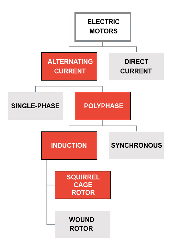
An electric motor is an electromechanical machine that converts electrical energy into mechanical energy. Electric motors fall into two broad groups: direct current (DC) motors and alternating current (AC) motors; alternating current motors are divided into single-phase and polyphase motors. Polyphase motors can be induction or synchronous. Then, induction motors can be wound rotor or squirrel cage rotor. The squirrel cage rotor motors are the most widely used engines in today's industry. Induction motors with squirrel cage rotors are relatively simple, very reliable, and low maintenance machines.
Induction motors operate under the principle of electromagnetic induction and are also known as asynchronous motors since their rotation speed (RPM) does not reach the synchronous frequency of the electromotive field. Induction motors are manufactured for various applications and requirements, operating speed, power, and efficiency, among other parameters, are considered for design, there are low, medium and high power motors, they are also manufactured to operate at various speeds; the amount of poles of an engine determines its operating speed.
| Number of poles | Synchronous Speed (RPM) depending on the Input Power Frequency | |
|---|---|---|
| 50 Hz | 60 Hz | |
| 2 | 3000 | 3600 |
| 4 | 1500 | 1800 |
| 6 | 1000 | 1200 |
| 8 | 750 | 900 |
| 10 | 600 | 720 |
| 12 | 500 | 600 |
| 16 | 375 | 450 |
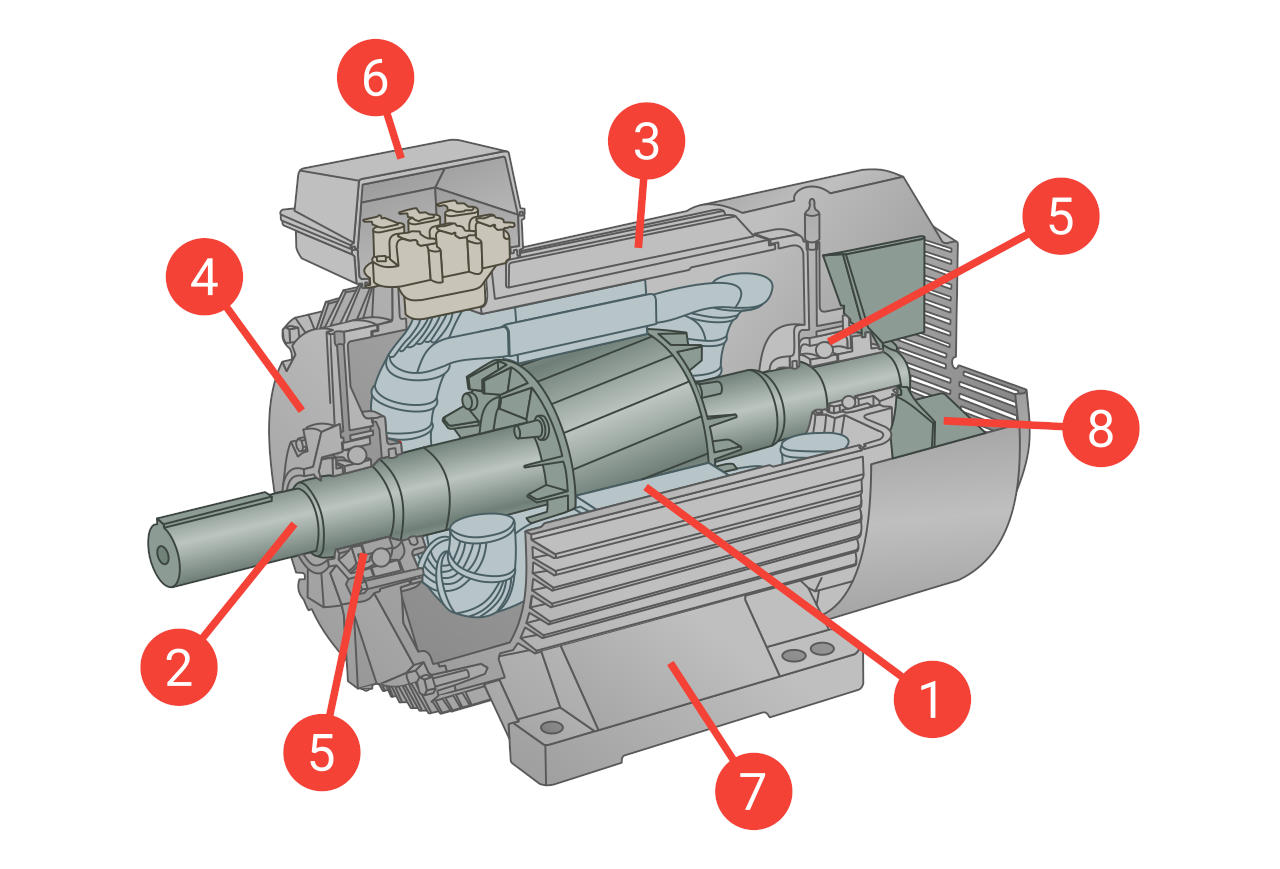
Main Components of an Electric Motor
The main components of an electric induction motor with squirrel cage rotor are:
- Stator
- Rotor
- Motor frame
- End shield
- Bearings
- Terminal Box
- Support base
- Cooling fan
Vibration measurement points
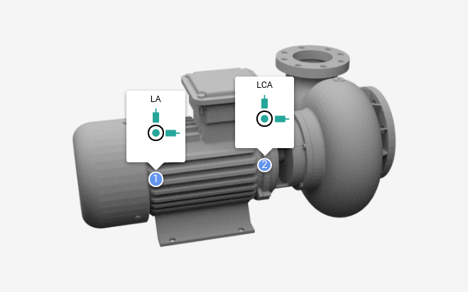
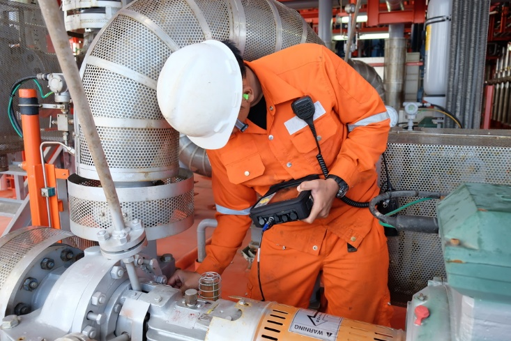
As we have already discussed in a general way in our article, "Where to place the vibration sensor", in an electrical motor, the measurement points for vibrations must correspond to the centerline of the shaft, on the bearing housing. Ensure a stable mounting on a solid part. Whenever possible, make measurements in the horizontal (H), vertical (V), and axial (A) directions of each bearing.
On the non-drive end position, it will not always be possible to place the sensor on the centerline, since the protective cover of the fan obstructs it, however, getting as close as possible to the bearing is recommended. Monitoring points should be marked, and data on the same locations are always taken. Some motor housings are made of aluminum; therefore, a magnet does not adhere; in these cases it can be held by hand by pressing firmly. Avoid the use of extensions as these suppress high frequency vibrations. In some applications, accessories are mounted for sampling vibrations; they are devices that are attached using glue or bolts, creating a fixed and firm to place an accelerometer.
Safety is the priority to select the vibration monitoring points; we must ensure that we do not make contact with rotating or hot parts, the safety in data collection takes care of the instruments and our health.
Typical failures in electric motors detectable by vibration analysis
 Imbalance
In electric motors, an imbalance is usually caused by one of the following causes:
- Wrong balancing procedure in workshop.
- Wrong selection of balancing quality grade.
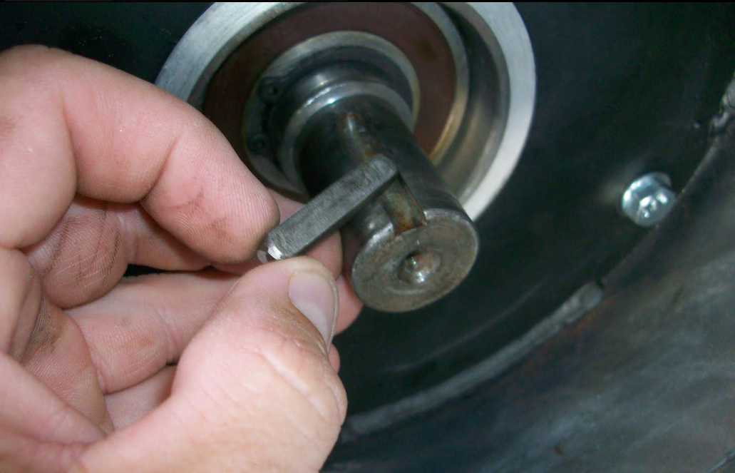
- Use of keyway out of specification.
- Do not consider keyway during workshop balancing.
- Deformation of the rotor due to excessive temperature.
- Wear or breakage of the cooling fan.
- Wear or breakage of the coupling.
- Breaking or improperly mounting the cooling fan.
When an imbalance is diagnosed in an electric motor, the following actions may be recommended:
- Review the operation and maintenance history to verify when the problem arose: in operation, after maintenance, new engine, etc. This will help with root cause analysis.
- Verify the procedures and the quality grade of balancing for the application.
- Inspect the coupling and cooling fan, verify its integrity and conditions.
- Perform a runout check to detect deformations in the rotor.
- Check the calibration of the balancing machine.
- Do a precision balancing according to the application, criticality, and characteristics of the motor.
- Check the cooling fan.
 Misalignment
In electric motors, misalignment is usually caused by one of the following causes:
- An inappropriate alignment procedure.
- Inappropriate calculation of alignment standards or tolerances.
- Thermal expansion.
- Weakness or inappropriate support base.
- Soft foot or wraped motor base.
- Failures in the coupling, excessive runout or deterioration.
When misalignment is detected in an electric motor, could recommend the following:
- Evaluate staff procedures and training.
- Do precision alignment by applying the relevant standards.
- Measure and correct soft foot.
- Evaluate the condition of the base and the coupling.
- Evaluate the influence of thermal expansion and consider this in the alignment procedure.
 Bearing issues
In electric motors, bearing problems are usually caused by one of the following causes:
- Bad assembly, excessive preload or wear of bearing housing.
- Failures in the lubrication procedure, excess or deficiency of lubricant.
- Lubricant of poor quality or incompatible with the application.
- Contaminated lubricant.
- Excessive vibration during operation.
- Grounding wiring failures.
When bearing issues are detected in an electric motor, the following actions may be recommended:
- Analyze the characteristics of the damage: corrosion, erosion, wear ...
- Evaluate the bearing assembly procedure.
- Verify the balancing and alignment.
- Verify the right selection of the bearing.
- Check the dimensions and tolerances of mounting in housing and rotor.
- Optimize the lubrication process.
- Check earthing wire.
 Eccentricity
In electric motors , eccentricity is usually caused by one of the following causes:
- Excessive wear of bearing or bearing housing.
- Wear in the rotor or bearing.
- Misalignment between housings.
- Deformation of the rotor.
- Eccentricity of coupling holes or pulleys.
When eccentricity is detected in an electric motor, the following actions may be recommended:
- Check alignment between bearing housing or motor end shields.
- Check wear on bearing housings.
- Measure the runout in coupling, pulleys, and rotor.
 Rotating looseness
In electric motors, rotating looseness or clearances are usually caused by one of the following causes:
- Wear of bearings or housing.
- Wear of babbit bearings.
- Bad adjustment of parts.
When gaps are detected in an electric motor, the following actions may be recommended:
- Dimensional checks on bearing housing, bearings and rotor.
 Structural issues
In electric motors, structural issues are usually caused by one of the following causes:
- Weak or damaged bases due to corrosion.
- Defective anchor bolts or bolts.
- Loose screws or anchor bolts.
When structural issues are detected in an electric motor, the following actions could be recommended:
- Evaluate the condition of the bases, both of the machine and the fundation.
- Evaluate the condition of the anchor bolts.
- Adjust bolts to the right torque.
 Electrical issues
In electric motor, electrical issues tend to originate from any of the following causes:
- Uneven air gap between rotor and stator.
- Loose or broken rotor bar.
- Poor quality of electric power: voltage imbalance, harmonics ...
- Failures from frequency inverters.
- Excess load.
- Excess of motor starts and stops.
- Insulation problems.
When electrical problems are detected in an electric motor, the following actions may be recommended depending on the symptoms:
- Perform a power quality analysis.
- Make a study of air gap and evaluate the origin (rotor/stator).
- Perform electrical tests on the motor (insulation quality).
- Evaluate the integrity of the connections in the rotor bars.
- Analyze the amount of successive startups.
 Resonance
In electric motors, resonance is usually cause by any of the following causes:
- Operate near a critical speed or natural frequency of the system.
- Changes in structural stiffness.
- Speed changes that bring the motor closer to a critical speed (variable speed motors).
When resonance is detected in an electric motor, the following actions may be recommended:
- Perform a test to calculate critical speeds.
- Make an impact test to verify if any natural frequency is being excited.
- Evaluate if the stiffness of the system has changed.
Other predictive technologies
Inspection of electric motors must be comprehensive, including dynamic, thermal and operational tests. The following technologies also apply to electric motors:
| Predictive technology | Detectable failures | |
|---|---|---|
 |
Thermography, in the motor and in the power circuit | Lack of heat dissipation (cooling), overload, faulty connection, friction, load or voltage imbalance. |
 |
Visual inspections | Dirt, abnormal noise, safety flaws, structural issues, integrity of the grounding, bad cooling, humidity, leaks, loose bolts, loose connection, missing parts, deterioration. |
 |
Ultrasounds | Bearing issues, electric issues, lubrication issues. |
 |
Oil analysis or tribology | Bad lubricant condition, contaminated lubricant: water, glycol, fuel, solids; Inadequate amount of lubricant, quality and applicability of the lubricant, bad lubrication procedure. |
 |
Power quality analysis | Load imbalance, voltage, frequency, amperage, isolation condition, condition of the rotor bars, electric harmonics, efficiency. |

Norms and standards
The permissible vibration limits for electric motors can be found in the ISO 10816-3 standard. The NEMA and IEC standards also establish some acceptance criteria.
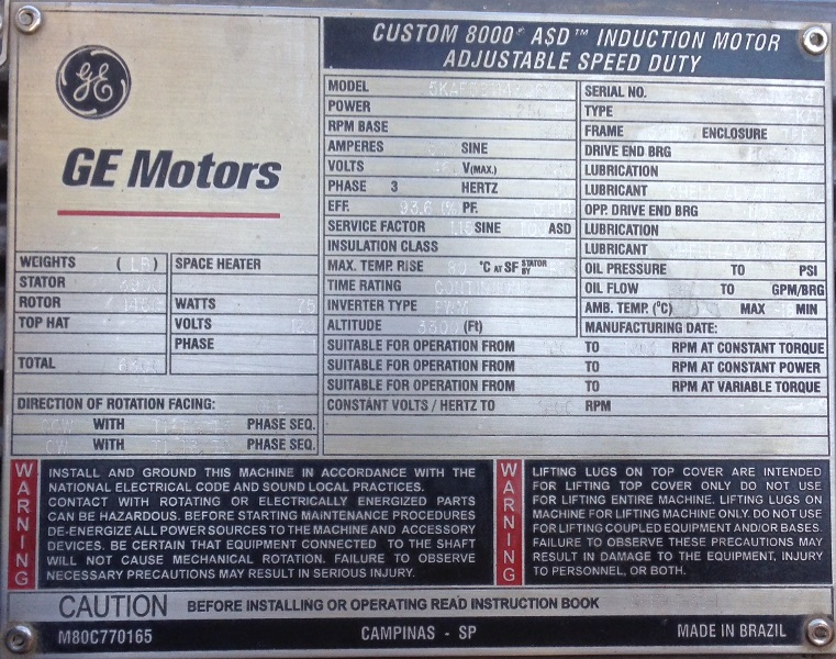
The engine nameplate
The identification plate is an essential source of useful information, and to understand it is a crucial factor; the plate data are parameters that should always be considered for reliable and efficient operation, effective inspection and proper maintenance. Operating a motor outside of its design limits will dramatically reduce its life and efficiency. Operators, inspectors, and maintainers must understand all these parameters and relate them to the operational and functional condition of the machine.
Locate the nameplate of the motors, protect it, and keep it in good condition. Solar radiation, environmental pollution and humidity affect the condition and readability of the plate.
What is Power-MI?
Power-MI is a cloud based solution that allows you to design & manage your condition-based maintenance plan integrating all techniques into one platform. Easy reporting, automatic work orders and CMMS integration.
Read more