Where to Place the Vibration Sensor

The location and installation of the vibration sensor are two of the most critical parts of the vibration data collection, which is why the reading point must be selected considering certain criteria.
The place in the machine where the vibration sensor will be placed is called the reading point. The sensor can be placed in one or more orientations or directions.
The vibrations on rotating machinery are generated by internal cyclic forces that cannot be directly measured. What is measured is the transmission of those cyclic forces through the structure of the machine; therefore, the vibration sensor measures the response of the mechanical impedance of the machine to those forces.
The good selection of the reading point has the objective of minimizing the effects of this mechanical impedance since what we are interested in measuring are the internal cyclic forces.
As a rule of thumb, the reading point must be located as near as possible to the support of the shaft (bearing or bushing). The attenuation of the signal is higher as you take the reading farther from the support.
Location of Reading Points
- The reading point must be accessible, and the safety of the operator must be guaranteed. Avoid exposure to rotating parts and high temperatures.
- The sensor must be placed as near as possible to the bearing or the bushing.
- The reading point must be accessible at all times and easy to identify to guarantee repeatability.
- The reading point must have an adequate surface to place the sensor temporarily.
- Do not measure on coverings, lids, moving parts, rotating shafts nor thermal insulation.
- Name or number the points in a clear, intuitive way and locate them in the route towards the direction of the power transmission.
Sensor Orientation at the Reading Point
For each reading point, two orientations are taken radial to the shaft of the machine and one axial.
Sensor orientations on horizontal shaft machines
- Radial horizontal.
- Radial vertical.
- Axial.
It is important to avoid tangent readings.
Radial orientations must be on the load zone of the bearing.
Since in most of the cases the radial vertical orientation cannot be placed in the inferior part, the superior part is the option.
For each reading point, two orientations are taken radial to the shaft of the machine and one axial.
Sensor orientations on vertical shaft machines
- Radial 1.
- Radial 2.
- Axial.
It is important to avoid tangent readings.
Radial orientations can be identified by the orientation, disposition of the machine, location in the plant. For example:
- Radial suction/discharge side.
- Radial electrical connection side.
- Radial door/tank/entrance side.
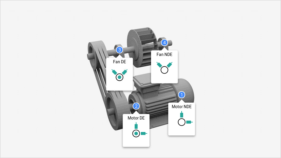
Sensor orientations on belt transmission machines
In machines with belt transmission, the load zone of the bearings varies according to the disposition of the components. The orientation of the reading points must be done adequately if the point is accessible.
As a priority, the radial vertical inferior orientation and the horizontal on the load side of the bearing must be taken.
If the radial vertical inferior orientation is not accessible, it will be taken on the superior part (the measuring tasks of the bearing must be executed in the horizontal orientation). Likewise, two readings can be taken at 45º inferior if the points are accessible.
If the radial horizontal orientations are not accessible, or accessible surfaces or fixing bolts at 45º want to be used, these must be used on the load side of the bearing.
If the inferior orientations at 45º are not accessible, both radial readings at 45º on the superior part must be taken.
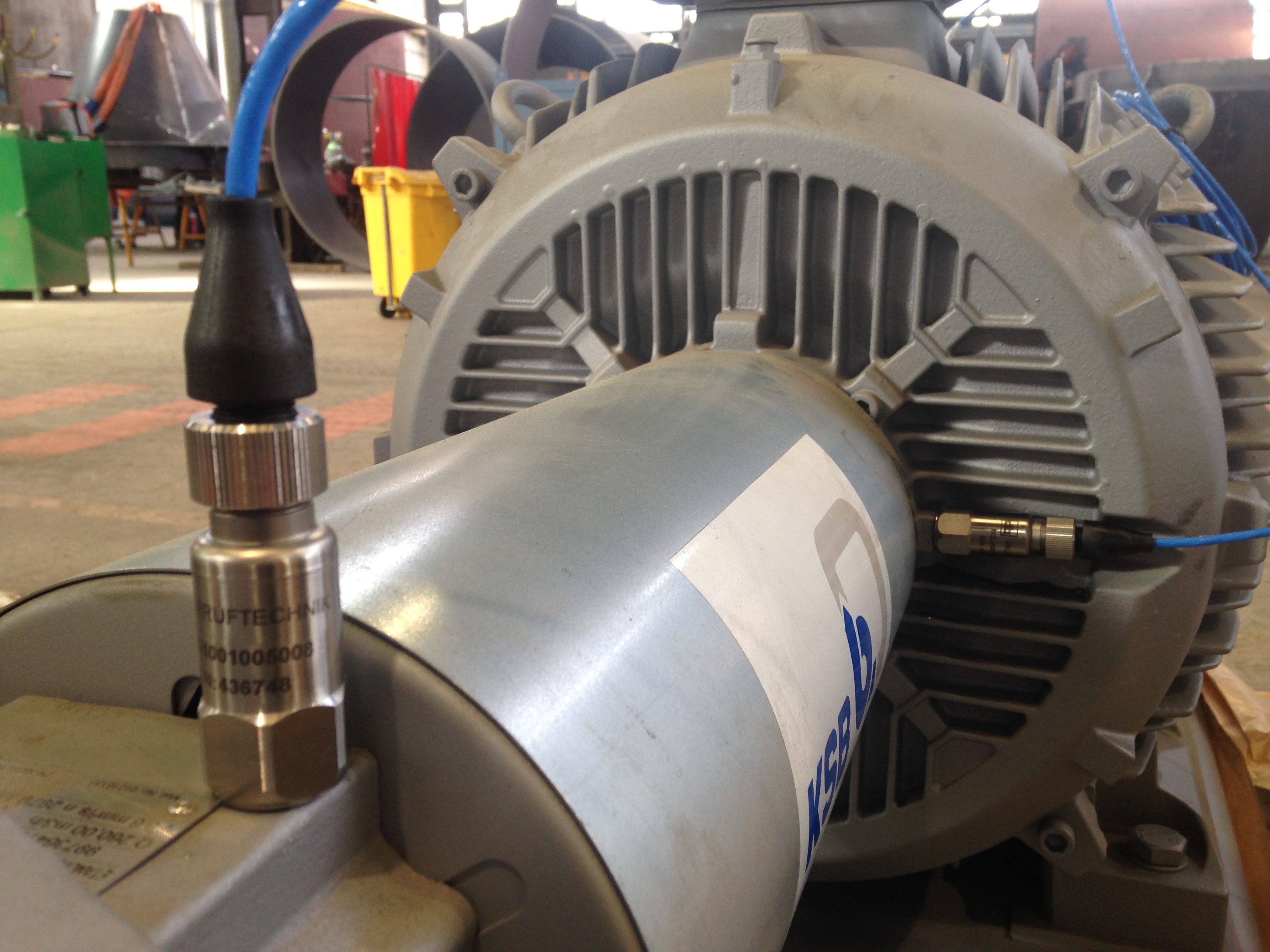
It is possible to substantially improve the quality of the vibration data collected by having access to the back part of the motor by machining the covering, provided that the cooling fan does not get exposed.
In case the machining of the back part of the motor is not possible or does not give access to a good surface for data collection, a washer can e added between the cooling fins of the motor as the last option. The data collection, in this case, will be done by means of a threaded sensor and a magnet.
What is Power-MI?
Power-MI is a cloud based solution that allows you to design & manage your condition-based maintenance plan integrating all techniques into one platform. Easy reporting, automatic work orders and CMMS integration.
Read more