Vibration Analysis of Reciprocating Plunger Pumps

A reciprocating pump has positive displacement, which means, it takes a fixed volume of liquid under suction conditions, compresses it (pressure increase) and it ejects it through the discharge nozzle. In this equipment, pumping the fluid is achieved by the alternating movement of a plunger, piston or diaphragm.
The reciprocating pump is not kinetic as it is the centrifugal one, and it does not require speed to generate pressure as high pressures can be obtained at low speeds. This is one of the advantages of the reciprocating pump, particularly to handle wash and abrasive pulps, and very viscous liquids.
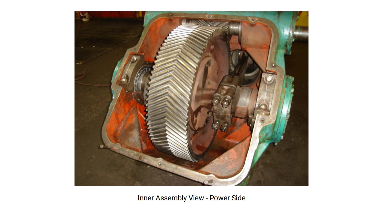
The reason to select a reciprocating pump instead of a centrifugal one or a rotating one must be the cost; not only the initial total cost, but also energy and maintenance costs. Figure 1 shows a typical assembly of this type of pumps.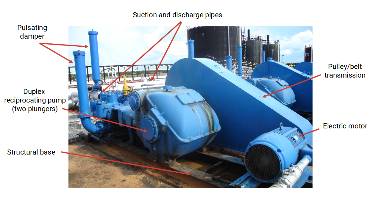
Some of the services or applications where reciprocating pumps are used include:
- High-pressure water cleaning (example: 20 gpm to 10.000 psig)
- Glycol and amines injection (example: 5 gpm to 1.000 psig).
- Fertilizer production. Ammonia loading (example: 40 gpm to 4.000 psig).
- Another application where the reciprocating pump is practically mandatory is to handle wash and abrasive pulps, or very viscous materials at more than 500 psig. Examples include from carbon wash pulp to peanut butter.
- Heavy, extra-heavy pumping in flow stations and oil pipelines.
- Sludge treatment in drilling operations.
- Injection and elimination of saltwater.
- Hydraulic systems and systems used to carry out hydrostatic testing.
- Cleaning, Dosing and Homogenization of fluids.
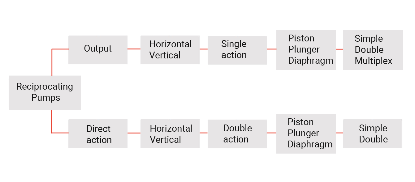
Pumps classification
Reciprocating pumps are generally classified by their characteristics as follows:
- Drive end, which means, output or direct action.
- Pumping element centerline orientation, which means, horizontal or vertical.
- Number of discharge strokes per rod cycle, which means, single or double action.
- Pumping element configuration: piston, plunger or diaphragm.
- Number of controlling rods, meaning, simplex, duplex or multiplex.
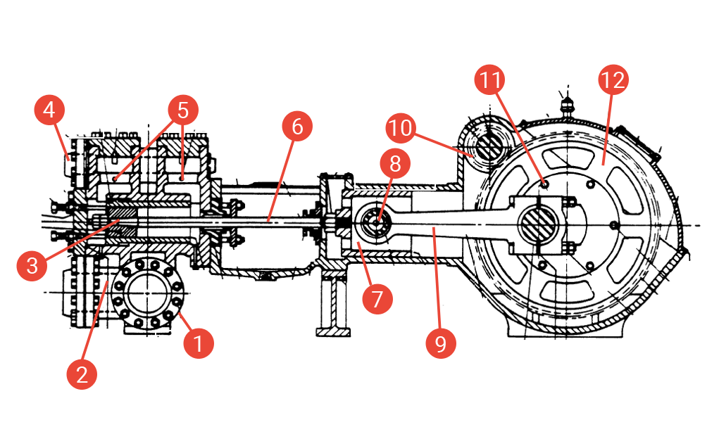
Main parts of a reciprocating plunger pump
The parts of a reciprocating plunger pump are:
- Suction pipes
- Suction valves in the pump body
- Plungers
- Discharge pipes
- Discharge valves in the pump body
- Plunger rod
- Runner
- Crosshead
- Crank
- Sprocket
- Crankshaft
- Gear rim
Most of these pumps are driven by electric motors or by inner combustion engines.
Fluid end components
The reciprocating plunger pumps have a pumping element that alternates in and out of the pumping chambers when operating. Each chamber includes, at least, a suction and a discharge valve. These are retention valves that open due to the differential pressure of the fluid and most of them operate under a spring load.
The Fluid End is the part of the pump where the pumping takes place. The components which are common in all of them are the cylinder for the liquid, the pumping element and the valves.
The cylinder for the liquid (case, cylinder liner) is the part that retains the pressure in the fluid end, and it is the most important part of the pumping chamber. It usually includes or supports all the other components of the fluid end.
A plunger is a flat and cylindrical disc installed on a rod, and it usually has some type of sealing rings. A plunger is a plain stick, and it can only be single action in its normal configuration. A plunger must seal against the cylinder or the case inside the pump.
The plunger pump usually has a replaceable case that absorbs the wear of the plunger rings. The sealing between the pumping chamber and the atmosphere is achieved by means of a cable gland, which includes packaging rings that adapt and seal against the inner diameter of the cable gland and the bar or stem.
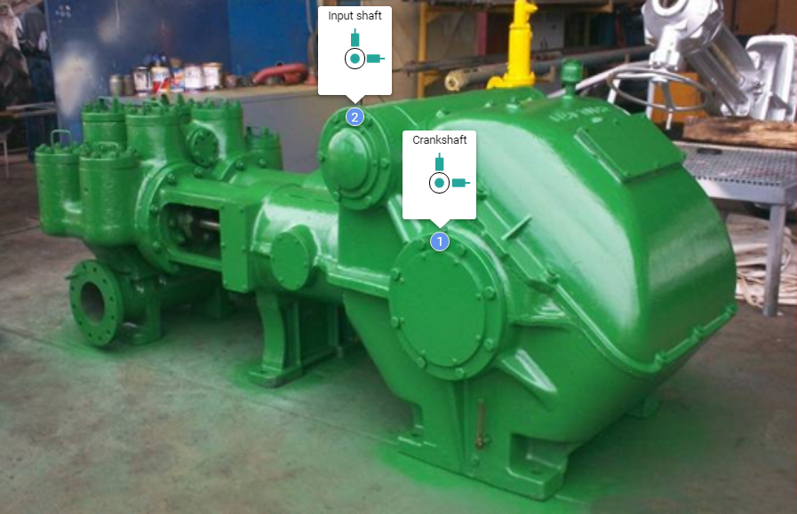
In this type of pumps, the usual transmission is by belts/pulleys in more than 90% of the applications, while the type of supports is usually roller bearings in the entry shaft where the sprocket is installed (fast shaft), and in the exit shaft where the gearwheel is installed (crankshaft or slow shaft); however, in a few applications flat bearings can also be used.
Vibration measuring points
As we have addressed in a general way in our article Where to Place the Vibration Sensor, in a reciprocating plunger pump, the vibration inspection points must correspond with the entry shaft or fast shaft, where the sprocket is installed, both on the pulley side and the opposite, as well as on the crankshaft, where the gearwheel is installed to measure on both ends. In addition, when possible, measurements must be taken in the horizontal (H), vertical (V) and axial (A) directions of each bearing. In total, it would be 4 measuring points or bearing supports at least (2 on each shaft), where 8 radial measurements would be taken (4V + 4H) and 2 axial measurements (1 on each shaft) at least. See Figure 4.
Safety is the priority when selecting the vibration monitoring points. A lot of care must be taken when placing sensors on both shafts, mainly in the area closest to the pulley with the bigger diameter (which is installed on the entry shaft) of the reciprocating pump, since there is a high entrapment risk. Based on this point, it is recommended to take axial measurements on the area opposite to the pulley.
The failures that can be detected by vibration analysis in reciprocating plunger pumps are:
Among the most important failures and by priority, there are:
 Imbalance
In reciprocating plunger pumps, imbalance usually happens due to one of the following causes:
- Imbalance in the pulley with the biggest diameter installed on the entry shaft of the pump.
- Imbalance of the entry shaft (fast shaft) or the reduction shaft (slow shaft, crankshaft) as a result of deficient manufacturing or wrong assembly of its components.
- Deficient balancing procedure at the workshop, bad quality of the balancing process.
When imbalance is detected in this type of pumps, the following actions are recommended:
- On-site balancing (on the field) of the pulley installed on the entry shaft.
- Disassembly, inspection and balancing at the workshop (bench machine) of the pre-assembled shafts.
- Verifying and improving the balancing procedures at the workshops.
 Misalignment
- Wrong alignment of its transmission system (belts/pulleys). It usually generates strong axial vibrations.
- Wrong assembly of the shafts, inadequate contact between the teeth of the entry sprocket and the gearwheel of the reduction shaft/crankshaft.
- Tension on the suction and/or the discharge pipes.
- Soft foot.
- Thermal expansion in the pump, the pipes and the structures.
- Improving the alignment of the pulleys and adjusting the tension of the belts.
- Verifying the alignment procedure, the standards applied, the instruments and the training of the personnel involved.
- Verifying the possibility of tension in the pipes and soft foot in the equipment.
- Calculating or measuring the thermal expansion in the equipment and using the data in the alignment process.
- Verifying the assembly of the pump at the workshop, ensuring the correct interaction between the teeth of the sprocket and the gearwheel (contact width and height between teeth, right backlash).
 Rub
Rub
In the reciprocating plunger pumps, the rub usually happens due to one of the following causes:
- Deficient lubrication in the bearings and gears.
- Deficient lubrication of the plungers and cases of the pump.
When rub is detected in these pumps, the following actions are recommended:
- Checking the lubricant levels, the condition of the lubricant (oil analysis) to determine possible replacement, as well as knowing which are the components rub and wear generation (wear particle analysis).
- Ensuring the lubricant used is the one recommended by the manufacturer of the pumps, or any oil equivalent in viscosity and other properties.
 Rotating looseness
In reciprocating plunger pumps, the rotating looseness usually happens due to one of the following reasons:
- Wear in the bearing housings, losing the adjustment in the outer race of the bearings.
- Shaft wear, losing the adjustment in the inner race of the bearings.
- Gear teeth wear and backlash increase (contact looseness between the sides of the teeth).
- Wear in the crankshaft, the shells and the rods of the pump.
- Wear between the shaft and the mounting hub of the pulley.
- Lack of adjustment or lack of tension in the transmission belts.
When rotating looseness is detected in this type of pumps, the following actions are recommended:
- External inspection, detection and adjustment of the mounting of the pulleys; improving the tension of the belts.
- Internal inspection of the pump during workshop interventions, either for partial or total maintenance, measuring looseness between components and replacing wearing parts.
- Verifying and improving the procedures of assembly and installation of pump components at the workshop.
 Structural looseness or structural issues
In reciprocating plunger pumps, structural looseness usually happens due to one of the following causes:
- Foundation issues (concrete fractures or cracks)
- Deficient attachment between the structural base and the foundation, or between the pump base and the supporting structural base. Loose bolts, deteriorated silentblocks.
- Structural base deformation.
When structural looseness is detected in this type of pumps, the following actions are recommended:
- Repairing the foundations and/or the structural base.
- Adjusting the attachment, verifying the right torque in each bolt.
- By measuring the phase, the existence of this fault can be verified.
- Replacing the silentblocks in case of damage.
 Bearing issues
In reciprocating plunger pumps, a bearing issue can happen due to any the following causes:
- Inadequate installation of the bearings on the equipment, lubrication issues, excessive load (working pressures), high working temperatures, normal wear due to life span.
- Misalignment and/or imbalance in the equipment.
- Outer race failing frequencies (BPFO) and/or inner race failing frequencies (BPFI), ball spin frequencies (BSF) and cage failing frequencies (FTF) rare present. All of them can be monitored by means of vibration analysis.
When a bearing issue is detected in a reciprocating pump, the following actions are recommended:
- Monitoring the condition by means of vibration analysis, ultrasound, among other techniques, in order to extend the life span and determine the right moment to replace the bearings.
- When replacing the bearing, performing a root cause analysis to determine the causes of the wear.
- Verifying and improving the bearing mounting and lubrication practices.
- Verifying the operational and process conditions (temperature, pressure, etc.)
 Flow issues
In reciprocating plunger pumps, a flow issue usually happens due to any of the following causes:
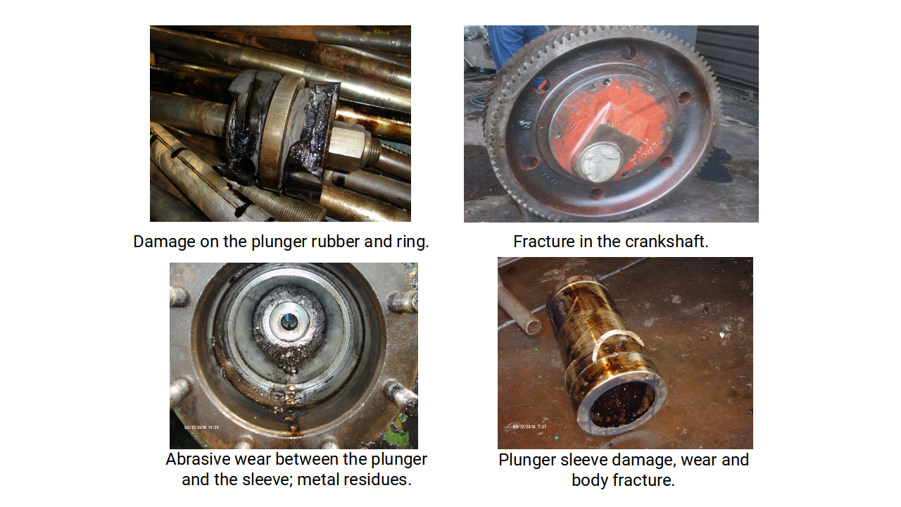
- Wear in the plungers and/or the pump casings. The volumetric flow rate is reduced inner recirculation.
- Obstruction in the suction pipe due to sediments or damage in the valves; low suction flow rate. Internal overheating in the pump due to a lack of working fluid.
- Obstruction in the discharge pipe or damage in the gate or check valves. Excessive pressure in the discharge line due to obstructions that may generate catastrophic failure in the equipment (fractures of the plunger rods, crankshaft damage, among others)
- Inadequate NPSH.
When flow issues are detected in this type of pumps, the following actions are recommended:
- Continuous monitoring of the volumetric flow of the equipment, comparing it against the ideal operating curve; in case there is not a flow meter in the line to measure constantly and automatically, the flow rate periodic measure must be planned and performed by means of portable ultrasound equipment. This action will allow to calculate the efficiency of the pump and plan the replacement of plungers and/or casings of the equipment, repairs of the valves, among other aspects.
- Constant check-up of the suction and discharge pressures; assessing the working temperatures; thermography applied in the suction and discharge lines may reveal obstruction according to the temperature patterns recorded.
 Resonance
In reciprocating plunger pumps, resonance usually happens due to any of the following causes:
- Excitation of a natural frequency of the equipment or the associated structures by a working frequency.
- Signals of this phenomenon are cracks, fractures of the structures, welds and bolted joints; the pulse generated by the alternative pumping of the fluids can also generate these faults.
When resonance is detected in this type of equipment, the following actions are recommended:
- Ensuring the right selection and adequate installation of a pulsation damper in the suction and discharge pipes of the pump.
- Checking the possible existence of resonance in the pump and associated structures; by means of vibration techniques, verifying the natural frequencies (bode diagram, spectral cascades); applying vibration isolation or damping techniques if required.
 Gear issues
In reciprocating plunger pumps, a gear issue usually happens due to any of the following causes:
- Deficient assembly of the gears on their corresponding shafts, for example, wrong mechanical clearance, incorrect axial positioning, among other assembly procedure errors.
- Deficient or incorrect contact between working gear teeth pairs; contact width and height between the sides of the teeth are incorrect; the clearance between the contact zones of the sides of the teeth may also be excessive due to a wearing process and it increases the vibration due to impact because of the backlash.
- Deficient design of the equipment gears; wrong materials or manufacturing processes in machine tools. Design problems in function to the number of teeth of the sprocket and the gearwheel (prime number relation, least common multiple), which may result in specific teeth having contact more frequently than others and creating uneven wear on some areas of the gears, which may result in unexpected cracks and fractures of these teeth.
- Gear teeth fractures as a result of excessive working loads in the equipment and the mechanical transmission. This can be the consequence of a high discharge pressure of the working fluid, which exceeds the design conditions and the safety factors, for example.
- Deficient lubrication of the gears.
 When gear issues are detected in this pump model, the following actions are recommended:
- Inspecting the inner gears of the pump, remove inspection caps from the casing and performing detailed inspections of the teeth, looking for cracks, fractures, abrasive wear, among other failure mechanisms.
- Performing wear particle analysis to determine the possible damage of the gears.
- Verifying the correct operation of the lubrication systems of the gears, the oil levels and the health of the lubricant.
- In case of damage evidence, the equipment must be removed and taken to the workshop for intervention and replacement of the damaged gears before a bigger failure is generated.
 Lubrication issues
In reciprocating plunger pumps, a lubrication issue usually happens due to any of the following causes:
- Contamination of the lubricant with external and internal agents.
- Degradación de la viscosidad, otras propiedades y aditivos del aceite lubricante. Degradation of the viscosity, other properties and the additives of the lubricating oil.
- Low lubricant level due to leaks or vaporization, among other causes.
When lubrication issues are detected in this pump model, the following actions are recommended:
- Completing the levels of lubricating fluid according to the specifications of the pump.
- Performing oil analysis to check the health of the lubricant, the condition of its properties and the additives.
- Performing wear particle analysis to determine the type and proportion of materials that are present in the oil and that are evidence of the wear of inner components of the equipment.
- Determine the need of total replacement of the lubricant according to the two previous actions.
Other predictive technologies
The following technologies also apply to reciprocating plunger pumps:
| Predictive technology | Detectable failures | |
|---|---|---|
 |
Thermography |
|
 |
Visual inspections |
|
 |
Oil analysis or tribology |
|
 |
Ultrasound |
|
 |
Alignment measurement |
|
Standards and norms:
ISO 14224 and API 689 to determine the border conditions and analysis limits in pumps, the failure modes, the failure mechanisms and the cause of failure.
API 674 for Reciprocating Plunger Pumps.
What is Power-MI?
Power-MI is a cloud based solution that allows you to design & manage your condition-based maintenance plan integrating all techniques into one platform. Easy reporting, automatic work orders and CMMS integration.
Read more