Phase measurement

The phase is a parameter closely related to vibration, since it appears in rotor balancing, detection of resonances and in the failures diagnosis in general. We will define the phase concept in two different ways for a better understanding:
- It is the time of advance or delay that has a vibrating wave with respect to another of equal period or with respect to a reference mark. The frequency of both vibration waves and the reference mark must be the same.
- Physically, the phase is the relative movement that has one point of the machine with respect to another.
The practical application of phase readings in fault diagnosis is in the differentiation of mechanical problems that manifest in the spectra in the same way, such as: imbalance, eccentricity, bent shaft, misalignment, looseness, flexible bed plate and resonance.
Technologies
Tachometric pulse
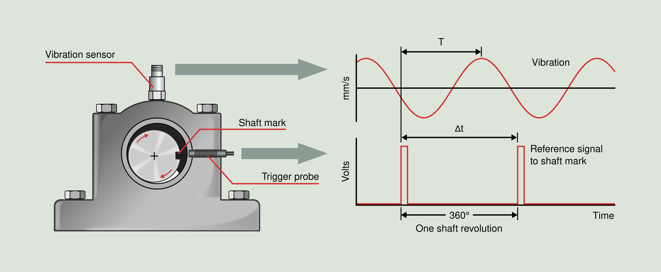
To carry out phase readings using a tachometric pulse, the following is necessary: a single-channel analyzer with TTL input and with a filter, a vibration sensor, a tachometer pulse generated by an optical or a magnetic pickup and a reference mark, that for the first case will be a reflective tape and for the second a shaft key. To carry out the measurement the vibration sensor is placed at the point to be analyzed and the tachometer is oriented towards the reflective tape or shaft key to obtain the tachometric pulse. The output of the tachometer is connected to the TTL input of the analyzer and the vibration sensor to its input. The TTL signal determines the frequency to be filtered and the user determines the bandwidth of the frequency through the analyzer. The analyzer will directly display the positioning of the maximum vibration of the filtered signal with respect to the reference mark.
The drawing of Figure 5.1 allows to clearly interpret the calculation of the phase performed in the single-channel analyzer. The calculation is a simple cross-multiplication that results in the following equation:
`sf "Phase" = sf "360" xx sf "∆t" / sf "T"`
The most important advantage of the infrared or visible light optical tachometer is the reliability, repeatability and rapidity in the realization of the readings, the main drawback being the need to stop the machine for the placement of the reflective tape. This is a drawback that magnetic tachometers do not have.
Strobe lamp
Phase readings with a strobe lamp can be performed using two different techniques. The first is fully equivalent to the tachometer pulse, in this case the lamp acts as a pulse generator at the frequency established by the user, usually the rotation speed of the shaft. The lamp has an output that sends the TTL pulse to the analyzer. In order for the pulse to always be generated at the same instant of each revolution of the shaft, the image of the shaft must always be frozen at the same position. In order to freeze the image always at the same position, it is necessary to manually tune the frequency of the lamp while focusing your attention on clear shaft marks or in the shaft key. The shaft must remain at the same position throughout all the measurements of phase. The value of the phase reading will appear on the analyzer display just as with the tachometer pulse.
The second phase reading technique does not show the phase reading in the analyzer, but is displayed according to the position of the shaft when is frozen by the strobe lamp. In this case the lamp does not send any type of signal to the analyzer. The set up is as follows, the analyzer filters the signal of the vibration sensor at the frequency established by the user, each time the analyzer detects the maximum vibration sends a signal to the lamp to emit a flash. These flashes are manually tuned to have the rotational frequency of the shaft, so the shaft seems to be frozen. Taking as a reference a fixed point, the phase is visually measured as the positioning of an axis mark with respect to the fixed reference.
The advantage of the lamp is that there is no need to stop the machine to place the reflective tape on the shaft and the disadvantage is that more time is required and the reading is less accurate than the one made with the optical pickup.
Multi-channel analyzer
Measurements with multichannel analyzers (with at least two channels) consist of performing at least two vibration readings with two sensors simultaneously and comparing their waveforms. The comparison will provide the phase of one of the measurements with respect to the other. By positioning a sensor in one of the machine points and placing another sensor sequentially in the points of interest we can make phase readings relative to the fixed sensor.
The main advantage of this method, besides its rapidity, is that it does not require the use of reflective tape or stroboscopic lamp. This technique is usually used for ODS analysis (operating deflection shape) and modal analysis.