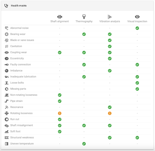
A key aspect of any effective predictive maintenance program is the ability to use multiple technologies to cover the most common faults or verify a fault using multiple technologies. This not only confirms the diagnosis but also enables more accurate and precise corrective recommendations.
Several technologies can be used in condition-based maintenance, but the most commonly used are:
 Vibration analysis
 Thermography
 Visual inspection
 Oil analysis
 Airborne ultrasound
 Shaft alignment
 Motor current analysis
Other commonly used predictive technologies are structure-borne ultrasound, liquid penetrant, insulation alternating-current (AC), power-factor test, time-travel analysis, and UV corona detection.

Each technology has a more or less specific field of application, being complementary, practically all of them. Below is a brief description of some of these technologies.
Vibration analysis
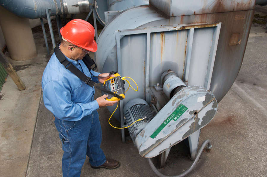
Vibration analysis is the most popular of the different technologies applicable to predictive maintenance. The reason for this is its versatility in detecting many defects in a wide range of machines, along with its reasonable initial economic investment.
Vibration is one of the clearest indicators of the health condition of a machine. Low levels of vibration indicate that equipment is in good condition, and when these levels rise, it is clear that something is starting to go wrong.
The equipment used for vibration data acquisition in industrial machinery ranges from portable data collectors to online or permanent monitoring systems.

Production and maintenance are the two areas of activity most closely linked to the productivity of an industrial installation. The management of process parameters (pressure, temperature, flow, etc.) has been subject of automation for more than a decade based on distributed control systems and networks of PLCs with Scada interfaces. On the other hand, managing maintenance parameters (vibration, temperature, etc.) for the same assets still has a long way to go before achieving widespread implementation and integration within the plant process network.
Vibration spectral analysis transforms a time-based signal into the frequency domain, where we can identify the characteristic vibration related to each of the components or defects that can suffer our asset.
It is not the appropriate time to delve into the details of each of the technologies that will be presented since each of them can be just on its own subject of dedicated training. However, it is good enough for the moment just to mention some of the problems that can be easily detected with vibration analysis: unbalance, misalignment, rotating or structural looseness, sleeve bearing lubrication problems, rolling element bearing damage, gear damage, electric motor issues, and hydraulic problems, etc.
In addition, a trend plot of overall vibration levels or vibration from a given frequency band is an extremely valuable tool for the supervision of our assets. Lastly, it is important to note the importance of establishing alert and alarm levels in order to optimize the analyses.
Thermography
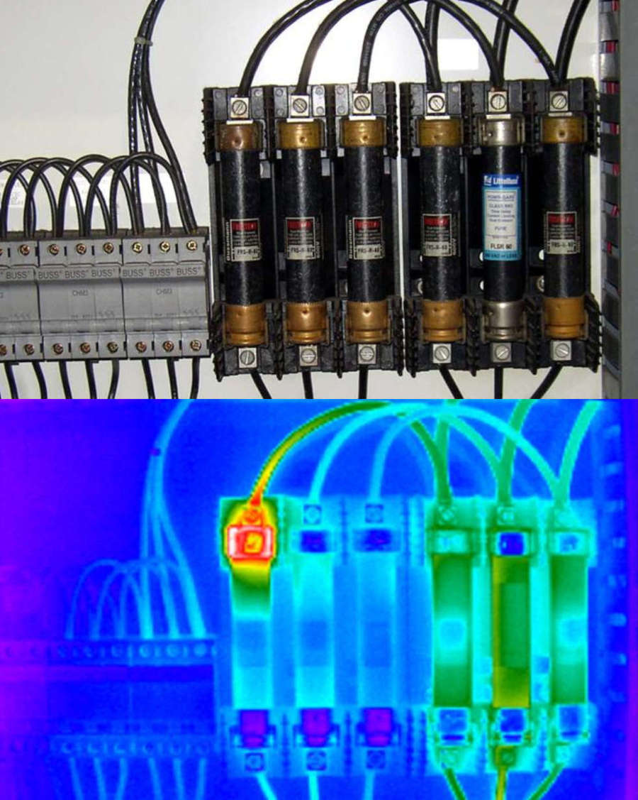
Infrared thermography could be briefly defined as a technique that allows, using the infrared radiation emitted by objects, the measurement of surface temperature. The instrument used in thermography to measure, is the infrared camera.

The main advantage of temperature measurement by means of thermography is that it is a non-contact measurement technique, so it will not affect the operation of the inspected assets. This capability makes it especially interesting in the control and maintenance of elements under high voltage. Amongst the main applications of thermography can be mentioned:
-
Thickness measurements and detection of discontinuities in thermal and refractory insulation materials.
-
Inspection of pipes and tubes.
-
Inspection in welding.
-
Positioning of components and faults in electrical circuits.
-
Fire prevention and detection applications.
-
Measurement in storage tanks.
-
Quality control in production processes.
From all potential applications, electrical installations are the most natural candidates for the application of infrared thermography. We can detect hot spots in the thermograms coming from such installations. The causes of these hot spots can be multiple:
-
Reflections
-
Radiation provided by the sun
-
Load
-
Emissivity variations
-
Heat induced by eddy currents
-
Increased resistance, caused by:
-
Loose connection
-
Dirty connection
-
Corroded connection
-
Connection with deteriorated adjustment
-
Wrong component
-
Incorrect installation
-
It will be the work of the thermography analyst to know how to discern, filter and evaluate any hot spots found in the thermograms, looking for the root cause and the origin of the issues.
Visual inspection
One of the simplest, but often neglected, forms of condition monitoring is visual inspection of machinery that more generally refers to making use of the human senses. Your eyes, ears and nose can be valuable condition monitoring tools and unlike other instruments, require little training to be utilized effectively. While this is subjective, you can often gain a good “gut feel” for where the problem is most severe. But remember, generally speaking the root cause cannot be determined in this manner.
Effective visual inspection procedures include examination of the machine and surrounding area for each of the following:
-
General cleanliness
-
Oil/fluids on surrounding machine
-
Oil/fluids on machine casing or bearing caps
-
Oil/fluids on coupling guard
-
Unusual marks
-
Visible leaks (lubricants, cooling water, etc.)
-
Lighting conditions
-
Local instrumentation for proper levels, temperatures, flows and amperage
-
Fretting and wear particles
-
Corrosion
-
Signs of overheating
-
Proper operation of slinger rings
-
Condensation/water in bearings
-
Differential temperatures, pressures and flows
-
Loose parts or components
-
Machine guard or cover condition
Another simple form of condition monitoring is audible inspection of machinery. While this is also subjective, you can often gain a good “feel” for the area where the source is originating. The use of stethoscopes, sounding rods and other listening devices can enable an experienced practitioner to detect such problems as rubs, bearing defects, cavitation, etc. When listening to a machine, try to determine if the sound is complex or simple, high frequency or low frequency, and from where the sound appears to be coming. Effective audible inspection procedures include examination of the machine and surrounding area for the following:
-
Sounds that are out of the ordinary
-
Humming
-
Squealing
-
Growling
-
Rubbing
-
Cavitation
-
Arcing/popping sounds
-
Hunting/beats
-
Noise from leaks
-
Comparison noise from bearings
-
Water hammer
-
Lifting sentinels/relief valves
-
Flow through system / components
Another inspection method or sense that may not have been considered is smell. The human sense of smell is powerful and can be used to identify various adverse machine conditions and lubricant problems. Among the common lubricant issues detectible by smell are certain types of contamination such as solvents, fuel, refrigerants and other process chemicals. Additionally, oil that has become significantly oxidized has a distinct odor that once observed, is easily identifiable. Some machine conditions are also detectible by smell. Slipping belts or overheated components will often present an alarming smell that demands investigation.
Oil analysis
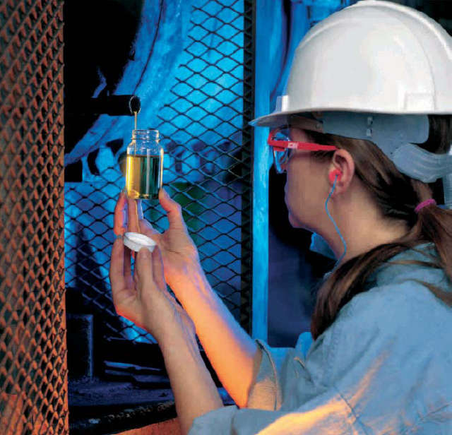
Oil analysis involves making physical and chemical tests to the oil in order to determine if the lubricant is still in good condition for use, or if otherwise it should be changed.

Ferrography, or wear particle analysis, however, uses the lubricant as a means to determine the condition of the lubricated machine.
Oil analysis in industrial facilities has two clear objectives: to know the state of the oil and to know the state of the machine. Traditionally the latter was neglected, always focusing on determining only the lubricant condition, for which a series of routine tests of viscosity, acidity, basicity, analysis of additives, visual inspections, etc. are carried out. This is not the goal of oil analysis as a predictive maintenance technique.
Spectrometry, ferrographs and particle contents provide valuable information on the condition of machine components that are bathed with our lubricants. We can detect defects much sooner than with other techniques such as vibration analysis.
In cases of critical machinery it should be used as a complementary technique to verify a diagnosis made, for example, with a vibration analysis. For instance, defects in rolling element bearings, sleeve bearings or transmissions can be confirmed by finding particles of them in a ferrogram.
Motor current analysis
The analysis of electric motors can be done using thermographies or vibration analysis, but another of the techniques that can be used to detect electrical or mechanical problems in AC motors is motor current spectral analysis (also known as MCA).
MCA is simply the process by which motor current readings are recorded and analyzed in the frequency domain. It has been around since 1985 and proven itself well over the years in locating rotor faults and air gap problems in motors.
On a practical level this technology can be performed in parallel with vibration analysis, using the same data collectors, but replacing the vibration sensor by a current clamp.
Mechanical faults related to belts, couplers, alignment and more are easily found through the use of a demodulated current spectrum, where is possible to identify and trend frequencies such as shaft speed, pole pass, belt pass, vane pass, gear mesh and bearing fault related.
MCA has proven to be a highly valuable predictive maintenance tool. Although it is a relatively young, rarely utilized technology, it is rapidly gaining acceptance in industry today.
Why should we care about finding mechanical faults with a demodulated current signal if we can already find them with technologies like vibration analysis or infrared thermography?
There are many reasons why using MCA to look for mechanical faults can benefit a condition monitoring program. For example, when it comes to belt and coupler problems, current will give an earlier and often more accurate fault indication than vibration analysis. The amount of energy created by the early stages of this type of fault is relatively low. When belts or couplers begin to wear, it is often not noticed in a vibration spectrum until the fault is nearing catastrophic failure. A demodulated current spectrum has the ability to detect the fault early enough to provide plenty of time to plan and schedule the repairs. However, demodulated MCA is not intended to take the place of a vibration program. It is best used as a complimentary technology to a good vibration program.
An added benefit of this technology would be in remote equipment locations or areas where equipment is not accessible during normal operations. On this type of equipment, visual inspections can be difficult, and the ability to perform vibration analysis is limited. Depending on the risk assessment, remote wiring transducers for vibration may be too costly. In this case, MCA would work well due to the ability of the equipment to be tested from the motor control cabinet.

 cloud_download