Basic Concepts Related to Principles of Infrared Thermography
Infrared Thermography considers the basic principles of physics, focusing on thermodynamics and electromagnetism.
Energy
All objects contain potential energy and kinetic energy. Potential energy is the energy stored in objects, such as electrical energy. Kinetic energy is the energy of motion, like molecular kinetic energy, enabling molecular vibration and defining the material's state.
Internal Energy or Thermal Energy
Internal energy is the sum of kinetic energy and electrical potential energy.
Temperature
Temperature is a measure of the average kinetic energy of molecules relative to the instrument used to measure it. It specifies a body's state regarding its ability to transfer energy to others. The temperature depends on the average kinetic energy per molecule, while the total Internal Thermal Energy is the total random kinetic energy of all molecules.
In science, the standard temperature measurement is based on the scale of absolute temperatures, where zero represents the theoretical temperature at which all molecular motion ceases. In the International System, units are expressed in Kelvin. To convert temperatures from Celsius to Kelvin, we can use the following formula:
K = °C + 273.15
Heat
Heat is defined as kinetic energy in transit due to the temperature difference of molecules, corresponding to the Second Law of thermodynamics. When this energy ceases to flow, it is said that thermal equilibrium has been reached. Heat is expressed in units of energy Joules (J) in the International System. The Joule is related to other units previously used for heat, such as calories and the British Thermal Unit (BTU).
1 cal = 4.186 J
1 BTU = 1055 J
Heat Transfer
Heat Transfer is the process by which thermal energy moves from one object or system to another due to a temperature difference. The theory of heat transfer fundamentally involves the understanding and application of the First and Second Laws of Thermodynamics. In summary, Heat Transfer is the mechanism by which thermal energy is transferred between objects or systems, following the principles of energy conservation and the natural flow of heat from hot to cold regions.
Hotspots
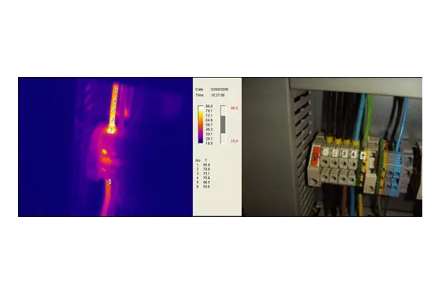
A hotspot is an area in the thermogram that indicates a higher temperature than the rest of the thermogram. Hotspots are physically generated by an increase in resistance in the contact area, where the dissipated power also increases. This is known as the Joule effect and is governed by the following law:
P = I² × R
Hotspots generate cycles of temperature increments that can lead to the failure of the components involved. The exact moment when this may occur is unpredictable; however, Infrared Thermography offers a predictive service that allows for timely identification.
A high ambient temperature may hide the hot spots by covering the entire object, while a low ambient temperature may cool the hot spots to a temperature below a predetermined threshold. These patterns, caused by sunlight, should not be confused with those generated by heat transfer. In addition, airflow cools the surface material, reducing the temperature differences between hot and cold areas. The mechanisms that allow thermal energy to be transferred from one body to another are governed by the principles of conduction, convection, and radiation.
Conduction
In the context of Infrared Thermography, conduction is a form of heat transfer that occurs through a solid medium, similar to how heat travels along a hot metal bar. It involves the transfer of thermal energy from regions of higher temperatures to regions of lower temperatures through physical contact between molecules, ultimately leading to a thermal equilibrium where the thermal energy and temperature become uniform throughout the material. Both the temperature difference and the material itself play important roles in this process. Conduction is unique as it is the sole mechanism of heat transfer that can take place in or from a solid, liquid, or gas whenever there is a temperature difference present.
In many cases, the energy measured in the first thousandth of an inch of a surface results from conduction. Fourier's Law for conduction allows us to deduce that the conductivity (k) and the thickness of the material (d), or the distance the energy must travel, influence the observed temperature difference (∆T) on the object's surface:
q' = -k × ∆T/d
Convection
In Infrared Thermography, convection is a method of heat transfer that occurs through a fluid, such as hot air rising from a heat source. Convection involves the transfer of energy from regions of higher temperatures to regions of lower temperatures through the movement of a fluid. This process involves temperature differences, a fluid medium, and a difference in pressure. Unlike conduction, convection involves heat transfer through the motion of molecules within a fluid or between a stationary solid and a moving fluid.
Convection poses challenges for Infrared Thermography as it disrupts most thermal models on the surface of objects, making it less beneficial for this technique. It can also reduce the radiation detected by the camera, causing small temperature issues to disappear entirely from the image. Additionally, convection tends to decrease not only the calculated absolute temperature but also the calculated temperature difference between components.
In Infrared Thermography, convection is identified as a faint and uneven thermal image. In the case of an area heated by convection, the thermogram may appear as a flame-like shape without clear boundaries of objects. Due to its effects on thermal imaging and the distortion it causes in temperature measurements, convection is a factor that must be carefully considered and compensated for during infrared inspections.
Radiation
Thermal radiation is the electromagnetic radiation emitted by an object as a result of its temperature; it does not require the presence of material and is strictly a surface phenomenon. It is the emission of energy through alternating electromagnetic waves.
Infrared Radiation
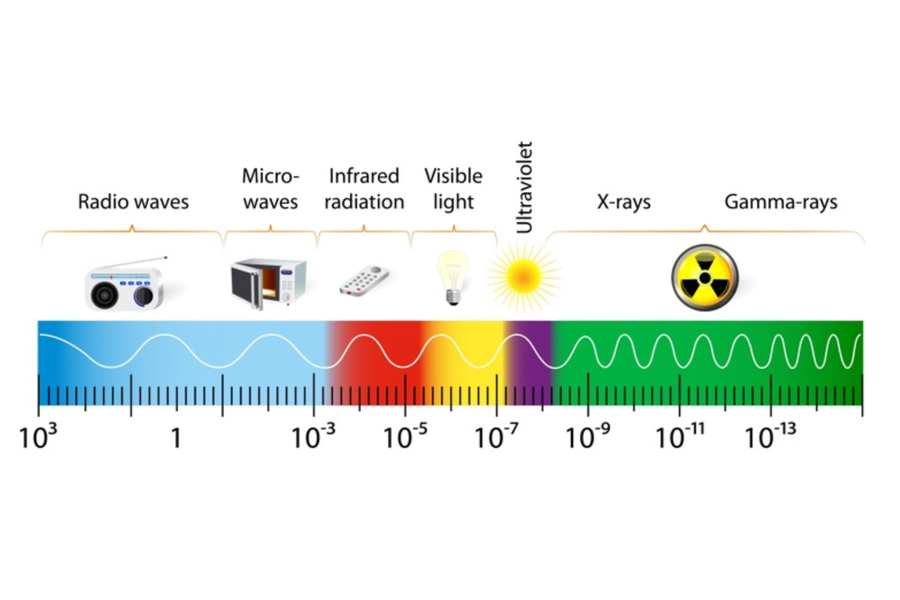
Infrared radiation is the emission of energy through a gas or vacuum from all objects whose temperature is above absolute zero, using alternating electromagnetic waves. This transfer of energy from objects (solids or liquids) at higher temperatures to objects (solids or liquids) at lower temperatures is known as energy transfer by electromagnetic radiation. Electromagnetic radiation is generated by the acceleration and deceleration of charged atomic particles. Electromagnetic energy can be transported as a wave with velocity, wavelength (λ), and frequency (f). All electromagnetic waves travel at the speed of light (c), which is a known constant of 3×10⁸ meters/second, and is described by the following formula:
λ = c / f
The wavelength of the infrared zone of the electromagnetic spectrum is between 1 and 1000 microns. All bodies above absolute zero continuously emit infrared energy through the emission of electromagnetic radiation and gain energy when they are in the presence of an appropriate medium by absorbing infrared radiation from other objects incident on them. Infrared radiation does not penetrate beyond one-thousandth of an inch in most solid or liquid materials.
Infrared radiation travels through gases and vacuum. If infrared radiation comes from the sun, it can affect the measurement quality due to reflections in metallic components and overheating of all components.
Instruments developed for Infrared Thermography, known as thermal cameras, can only "sense" infrared radiation; they do not measure temperatures but measure the thermal energy radiated and convert this information into temperature values.
The total irradiated energy (ETI) that an infrared system perceives can have as its source emission (E), radiation (R), and transmission (T). Therefore, the energy incident on its detector and forming the image on its screen can be expressed as:
ETI = E + R + T = 1 unit or 100%
In reality, most of the objects we see have no transmission value, so we can use the formula as:
ETI = E + R = 1 unit or 100%
The study of infrared radiation is based on theories and laws related to a theoretical object known as a black body.
A black body is a theoretical object that emits a maximum amount of energy at all temperatures and in all wavelengths. Therefore, it is a perfect emitter and absorber of energy.
The laws of infrared radiation are based on the behavior of a black body.
Stephan-Boltzmann Law (Joseph Stephan 1879, Ludwig Boltzmann 1884).
Stephan and Boltzmann determined that the amount of energy radiated by an object is proportional to the temperature of the object (in Kelvin) raised to the fourth power. This means that a small change in temperature represents a large change in the radiated energy, explaining why infrared systems are so sensitive to small changes in energy. The formula to determine the amount of energy emitted by an object due to its absolute temperature is:
Q = 5.67×10⁻⁸×T4
Wien's Law (1893).
Wien's law determines the wavelength, in microns, at which the maximum amount of energy is emitted by an object at any specific temperature in Kelvin:
λmax = 2898 / T(Kelvin)
Planck's Law (1900).
Planck's law describes the spectral distribution of energy at any specific temperature and over the entire range of wavelengths. It is graphically represented by the so-called Planck curves.
Emissivity
Understanding the concept of emissivity and its application in Infrared Thermography measurements is directly related to the accuracy of temperature measurements. Objects with different materials and surface conditions have varying emissivity values, which influences the amount of thermal radiation they emit. If emissivity is not taken into account, thermal imaging can provide erroneous information and lead to inaccurate diagnoses. Therefore, mastering the concept of emissivity increases analytical skills and diagnostic accuracy. Understanding emissivity is essential for precise temperature calculations and reliable thermal analysis. By accounting for emissivity in our Infrared Thermography, we ensure more accurate results and enhance our capabilities in diagnosing and interpreting thermal patterns effectively.
Emissivity, in the context of Infrared Thermography, refers to the measure of an object's ability to emit thermal radiation relative to that of a perfect blackbody at the same temperature and wavelength. The emissivity (ε) is the ratio at which an object emits energy compared to a blackbody at the same temperature and wavelength. In other words, it represents the relationship between the radiation emitted by a blackbody at a certain temperature and the radiation emitted by the machine or component being analyzed at the same temperature. The emissivity is expressed as:
Emissivity = (Radiation emitted by the object at temperature T) / (Radiation emitted by a blackbody at temperature T)
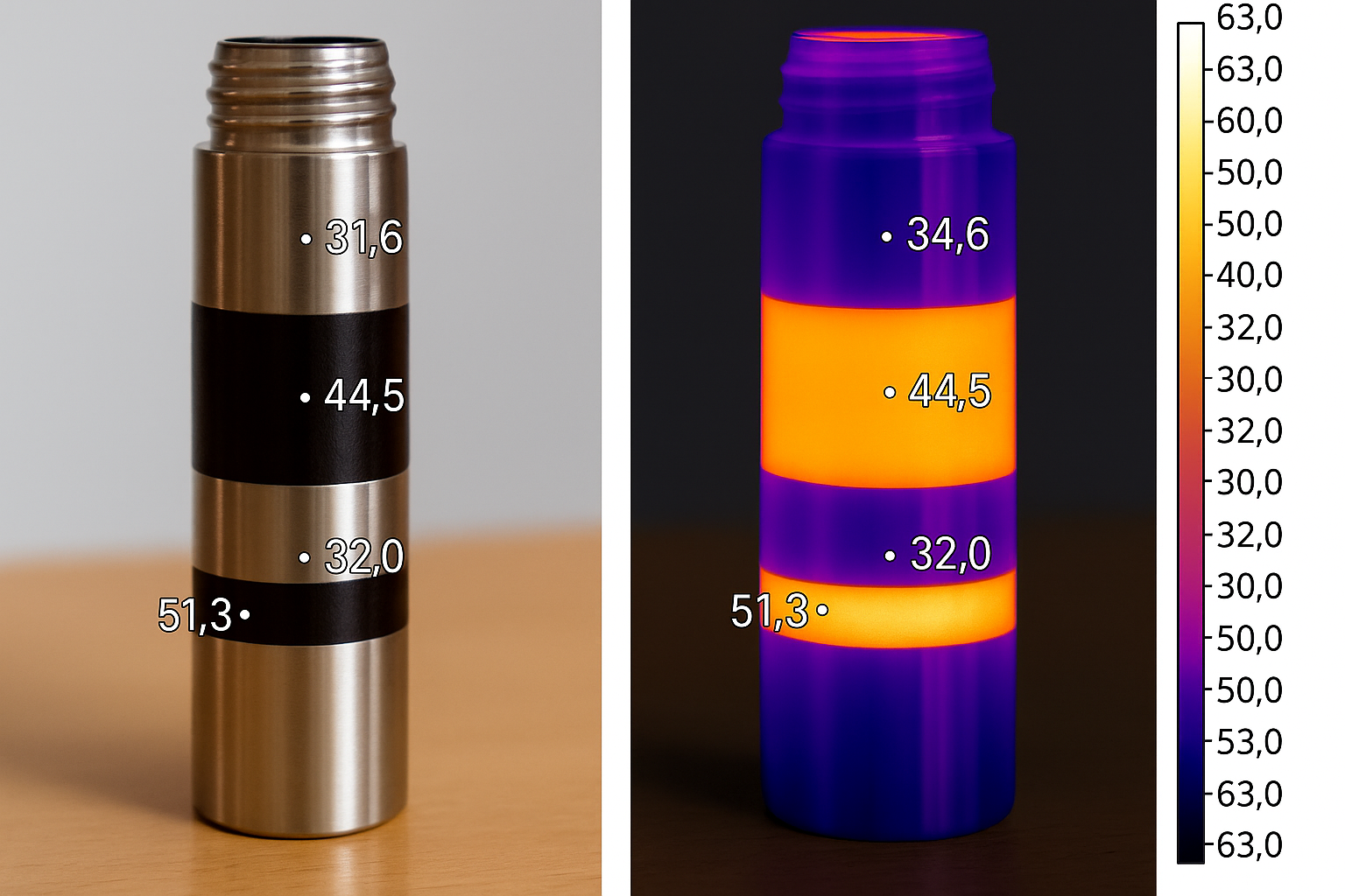
Therefore, emissivity is an expression of an object's ability to emit infrared energy. Two objects can physically be at the same temperature, yet the thermogram shows them at different temperatures. This is due to the difference in emissivity between the two objects. Objects that are easily detected by infrared cameras are considered good emitters and have an emissivity close to unity (ε ≈ 1). Conversely, objects that are difficult to detect with an infrared camera are poor emitters and have an emissivity close to zero (ε ≈ 0).
A blackbody is an object with an emissivity equal to 1. A real or spectral emitter has an emissivity of less than 1 and greater than 0, while a perfect mirror has a 100% reflection and, therefore, an emissivity of 0.
The emissivity of an object is determined by the following characteristics:
- Type of material of the object.
- Conditions and surface finish of the material (polished, oxidized, etc.).
- The temperature of the object.
- Wavelength.
- Surface geometry (cavity effects, etc.).
The main characteristics that affect emissivity are the type of material of the object and the surface condition. The values of emissivity can vary from one material to another. Metals with rough or oxidized surfaces generally exhibit higher emissivity compared to polished surfaces.
| Material |
Emissivity |
| Aluminum - Freshly polished |
0.04 |
| Aluminum - Aged, Oxidized, Discolored |
0.90 |
| Asphalt |
0.93 - 0.95 |
| Ceramic and Brick |
0.80 - 0.95 |
| Fabric |
0.95 |
| Concrete |
0.94 - 0.95 |
| Copper - Fresh |
0.04 |
| Copper - Oxidized |
0.40 - 0.98 |
| Electrical tape |
0.95 |
| Glass |
0.76 - 0.85 |
| Painted surfaces |
0.74 - 0.96 |
| Paper |
0.50 - 0.95 |
| Plastic |
0.95 |
| Sand |
0.90 |
| Snow |
0.82 - 0.89 |
| Soil |
0.90 - 0.98 |
| Steel, Iron - Oxidized |
0.65 - 0.95 |
| Stainless Steel |
0.10 - 0.80 |
| Water |
0.93 |
| Wood |
0.89 - 0.94 |
| Human Skin |
0.98 |
| Aluminum Foil |
< 0.04 |
Human skin behaves as an excellent natural emitter, closely resembling a black body with an emissivity of 0.98. On the other hand, aluminum foil behaves more like a mirror with an emissivity that can be lower than 0.04. There exists a relationship between emissivity and reflectivity, and for opaque bodies, this relationship is established as follows:
Emissivity + Reflectivity = 1.0
Thus, a highly reflective material would be a poor emitter of infrared energy, leading to a low emissivity value. In practical applications, when determining emissivity using an infrared system, it is required to use an Infrared Thermography camera with the same wavelength that will be used for temperature calculations. Additionally, the object, the environment, and the background must be at different temperatures for accurate measurements. Understanding these emissivity principles is vital for conducting precise Infrared Thermography inspections and interpreting thermal patterns effectively as experienced Infrared Thermography analysts.
Emissivity Test (ISO 18431-1): To determine the unknown emissivity of an object.
- Place a black tape (ε ≈ 0.95) on the object with unknown emissivity. Allow a few minutes for thermal equilibrium, during which the tape acquires the same temperature as the object.
- Calibrate the equipment from its internal menu before measuring the temperature of the tape.
- Measure the temperature of the tape while adjusting the thermogram's emissivity to 0.95, noting the recorded temperature value.
- The previous reading can be labeled as Point A, with both emissivity and temperature values known. A second point, Point B, will have a known temperature because the tape has taken on the object's temperature.
- Aim the instrument at the object and locate Point B using the pointer on the thermographic camera's display. Adjust the object's emissivity until the temperature value matches the one obtained in Step 3.
This test must be repeated at least three times to ensure the validity of the test values. Compliance with standardized test procedures and accurate emissivity calculations is essential to obtain reliable thermographic data during our inspections.
Ambient Reflection
Reflection is a critical factor that significantly impacts the accuracy of temperature calculations when analyzing thermal images or thermograms. It introduces false temperature values representing radiated energy from the background, energy reflected on the object and directed to the infrared system's lens.
To address this issue, the ISO 18434-1 standard outlines a direct method for measuring reflection:
- Identify the area on the object from which the reflection originates.
- Set the camera's emissivity value to 1.
- Use the spot meter, point measurement function, isotherm, or area selection to determine the average temperature of the background in that area.
- Introduce this false temperature into the ambient reflection function of your system.
By applying this method, when the object and the ambient background are at the same temperature, the apparent emissivity tends to be close to unity. Understanding and accounting for reflection in our measurements is crucial to ensure accurate and reliable temperature readings, leading to more precise diagnoses and effective thermal analysis in various applications.


 cloud_download