Frequencies of a gear assembly

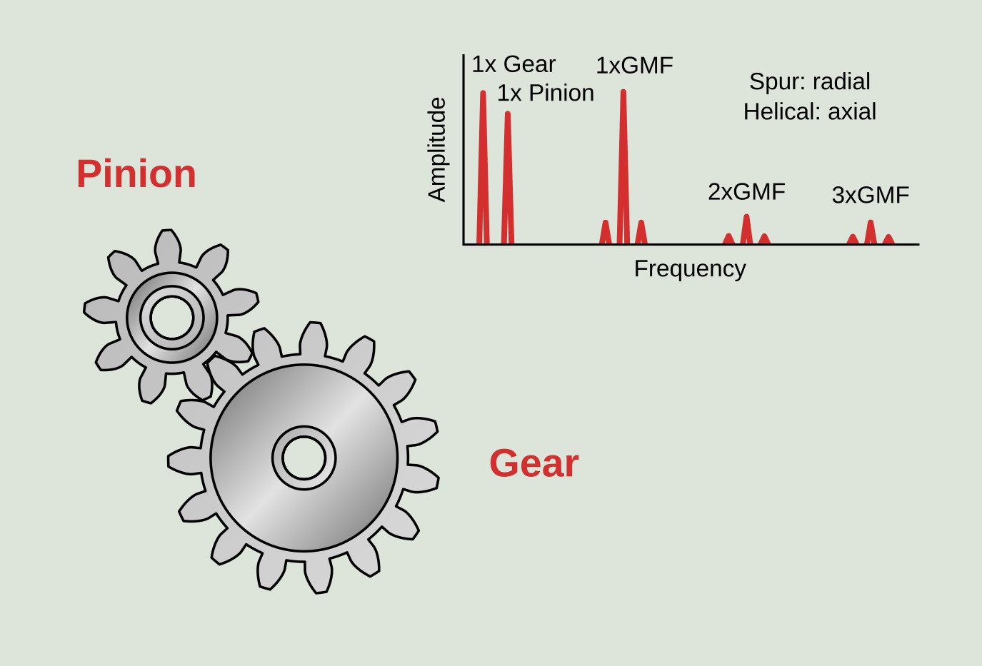
The location in the spectrum of all the gear related frequencies requires the knowledge of a minimum amount of gearbox data. These data are the rotating speed of the input shaft or the output shaft and the number of teeth of the different gears. In this way there will be no doubt in the identification of the gear frequencies and their sidebands. The frequencies associated directly with a gear assembly are as follows:
- Gearmesh frequency (GMF): is characteristic of each gear assembly and appears in the frequency spectrum regardless of the condition of the gears. Its amplitude depends significantly on the load at the time of reading. It is calculated according to the following formula where, Z is the number of teeth and RPM is the rotating speed of the gear.
`sf "GMF" = sf "Z"_sf "P" xx sf "RPM"_sf "P" = sf "Z"_sf "G" xx sf "RPM"_sf "G"`
- Gearmesh frequency side bands: these are frequencies equidistant from the gearmesh frequency. These sidebands correspond to the rotating frequency of the pinion and the gear. They are very important in the diagnosis of the gear assembly, since they indicate if the gear or the pinion are in bad condition.
- Hunting tooth frequency (HTF): to calculate it the number of assembly phases (NA) must be calculated in advance as described in the following section. Indicates the frequency with which a tooth of the gear engages with the same tooth of the pinion. In case of damage to one tooth of the gear and another of the pinion, the maximum vibration will occur when both faults come into contact. This frequency is very low so it is difficult to locate in the frequency spectrum, being detected more easily in the time waveform.
`sf "HTF" = (sf "GMF" xx sf "N"_sf "A") / (sf "Z"_sf "P" xx sf "Z"_sf "G")`
- Assembly phase frequency (APF): indicates that as a result of wear, the space between teeth and the teeth profile has changed.
`sf "APF" = sf "GMF" / sf "N"_sf "A"`
- Gear natural frequencies: when some kind of gear deterioration develops the natural frequencies of the gears can be excited.
- Ghost or phantom frequencies: correspond to a relatively rare defect that shows up as a frequency typically higher than the GMF but not directly related to the geometry of the gear. It is due to manufacturing errors that are driven by vibration from the manufacturing drive train and can be typically traced to the number of teeth and speed of the cutter machine.
Calculation of the number of assembly phases
The concept of assembly phases is defined as the different modes of engagement between a pair of gears. In the following figure a pair of gears is presented, one with 15 teeth and the other with 9. The teeth of the two wheels are numbered and it is possible to find out graphically that there are three different ways of assembling the gear. This means that there are three possible wear patterns when engaging the gear and pinion. For the gear-pinion pair of our figure would be: first assembly phase, mounting the tooth number 1 of the pinion between the teeth 1 and 15 of the gear; Second assembly phase, mounting pinion tooth number 2 between teeth 1 and 15 of the gear; Third assembly phase, mounting pinion number 3 of the pinion between teeth 1 and 15 of the gear.
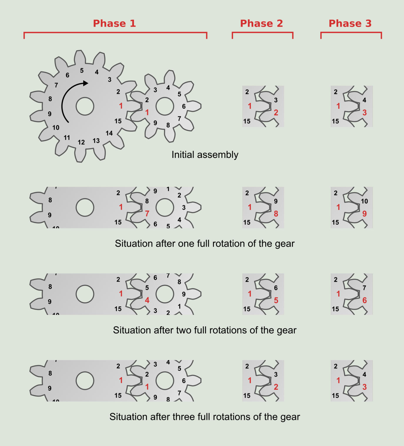
The mathematical method for calculating the assembly phases (NA) is done by calculating the greatest common divisor of the number of teeth of both gears. In our particular case of the 15 teeth gear, its prime factors are 5, 3 and 1, since 5x3x1 is 15. The prime factors of the 9 teeth pinion are 3x3x1. The maximum common divisor is 3x1 which is 3, the same number that had been graphically obtained.
Each pinion tooth will enter to meshing with ZG/NE gear teeth as each tooth of the gear will enter to meshing with ZP/NE of the pinion. For the particular case of the diagram of the assembly phases, it is observed that one tooth of the gear always engages with the same three teeth of the pinion.
Planetary gears
Another type of speed reduction or multiplier gearboxes are those that have planetary gears. The following figure shows the components and basic structure of planetary gears.
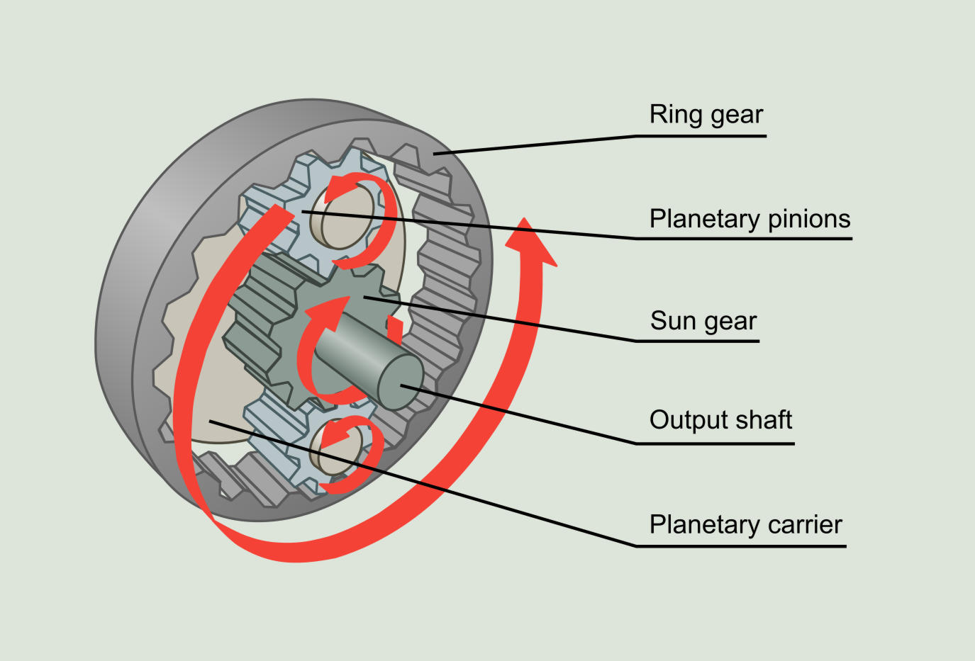
The input shaft ends in a plate called planetary carrier. The planetary carrier is attached to each of the planetary pinions through a shaft. Around the planets there is a large and stationary gear, called ring gear. The planets mesh simultaneously with the ring gear and the sun gear, which is the gear connected to the output shaft.
Its gear ratio is calculated as follows:
`sf "G"_sf "R" = 1 + sf "Z"_sf "RING GEAR" / sf "Z"_sf "SUN GEAR"`
where Z refers to the number of teeth of a given gear.
The rotating speed of each of the planetary pinions is calculated as follows:
`sf "RPM"_sf "PLANETARY PINION" = sf "RPM"_sf "CARRIER" sf "Z"_sf "RING GEAR" / sf "Z"_sf "PLANETARY PINION"`
The gearmesh frequency of a planetary gear system is:
`sf "GMF" = sf "Z"_sf "PLANETARY PINION" xx sf "RPM"_sf "PLANETARY PINION"`
A defect in the ring gear can be seen at a frequency equal to the number of planetary pinions multiplied by the rotating speed of the planetary carrier. A defect in the sun gear will be detected at a frequency equal to the number of planetary pinions multiplied by the rotating speed of the sun minus the rotating speed of the planetary carrier. Finally, a defect in a planetary pinion will appear at a frequency equal to twice the rotating speed of the planetary pinion.
En esta página:
¿Qué es Power-MI?
Power-MI es una herramienta en la nube que le permite diseñar y gestionar su mantenimiento predictivo con todas las técnicas en una plataforma. Informes fáciles, órdenes de trabajo automáticas e integración a CMMS.
Leer más¿Te gusta esta formación?
 cloud_download¡Descarga aquí nuestra versión en formato eBook!