Misalignment

Misalignment is one of the most frequent vibration problems in rotating machinery and is due to the difficulty of the alignment of two rotors with their respective supports. Misalignment can happen due to very different causes such as: excessive reliance on the use of elastic couplings and self-aligning bearings, machine deformation during operation that leads to displacements of the driving or driven system, etc. Misalignment will produce very high levels of vibration in the vicinity of the coupling that can precipitate bearing degradation, coupling blocks wear, bolt breakage, driver overheating due to an increase in the electrical power consumption, etc., so it is recommended to correct it before it causes additional considerable damage that can lead to a machine stop.
Offset misalignment can be measured using dial indicators and corrected with shims under the feet of the machine's free system (usually the motor). At present, there are available very accurate pieces of equipment for the measurement and correction of misalignment, based on brackets to support the dial indicators and even laser systems. These systems rely on instruments for automatic measurement, calculation of applicable corrections and on-screen display of tolerances and correction offsets.
Misalignment occurs when there is little accuracy in the alignment between pairs of components, such as coupling elements, bearings, shafts and pulleys. Misalignment usually manifests with strong vibration in the axial and radial directions. Axial readings can present the first harmonics of the rotating speed, 1x, 2x and 3x RPM. Radial readings normally exhibit activity at 1x and 2x RPM. Low amplitude at the third harmonic frequency and at higher harmonics. However, in some machines the predominant vibration due to misalignment occurs at 1xRPM and may be mistaken with unbalance. In these cases it is recommended to perform a phase analysis that will allow to distinguish between problems of unbalance and misalignment. On the other hand, the time waveform is characterized by a repetitive pattern with no impacts in acceleration.
A phase analysis allows us to confirm the diagnosis of misalignment and is characterized by an important phase difference between the bearings closer to the coupling in the same measurement directions. Another symthom of misalignment is that the phase difference between horizontal readings is not similar to the phase difference between vertical readings.
Types of misalignment
There are two types of misalignment, angular misalignment and offset or parallel misalignment that are described below. In most cases real world misalignment is a combination of both.
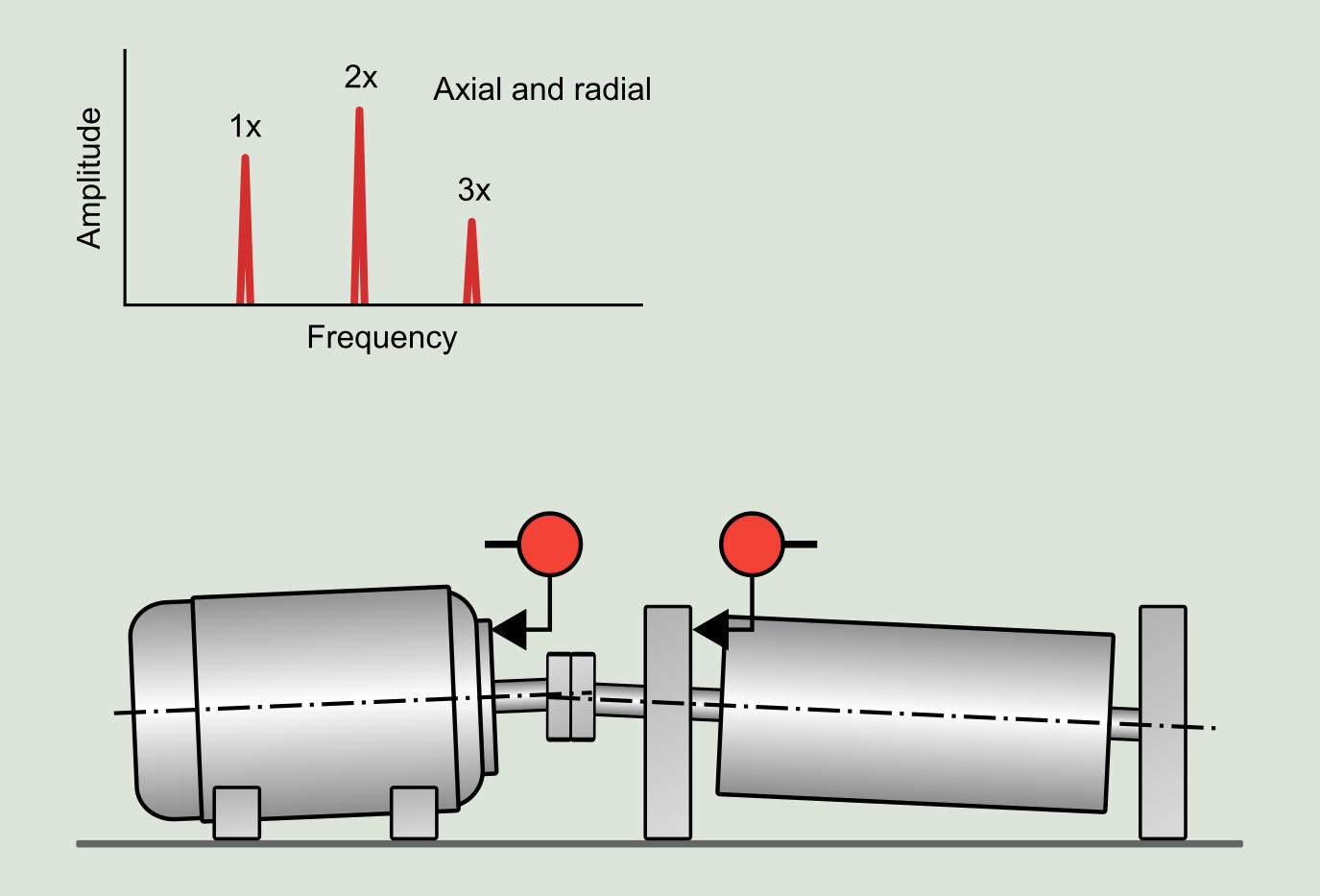
Angular misalignment
There is angular misalignment when the center lines of two shafts are crossed at an angle. The presence of strong axial vibration at 1x RPM characterizes this type of misalignment, which may be accompanied by harmonics of the shaft rotating speed with low amplitudes.
Symptoms:
- Strong axial vibration at 1x RPM possibly with 2x and 3x harmonics.
- The 2x RPM harmonic in the axial direction can reach a value equal to or even higher than 1x.
- Vibration in the radial direction, probably of smaller amplitude than in the axial direction, in 1x, 2x and 3x.
- The axial phase measurements on both sides of the coupling are 180° out of phase.
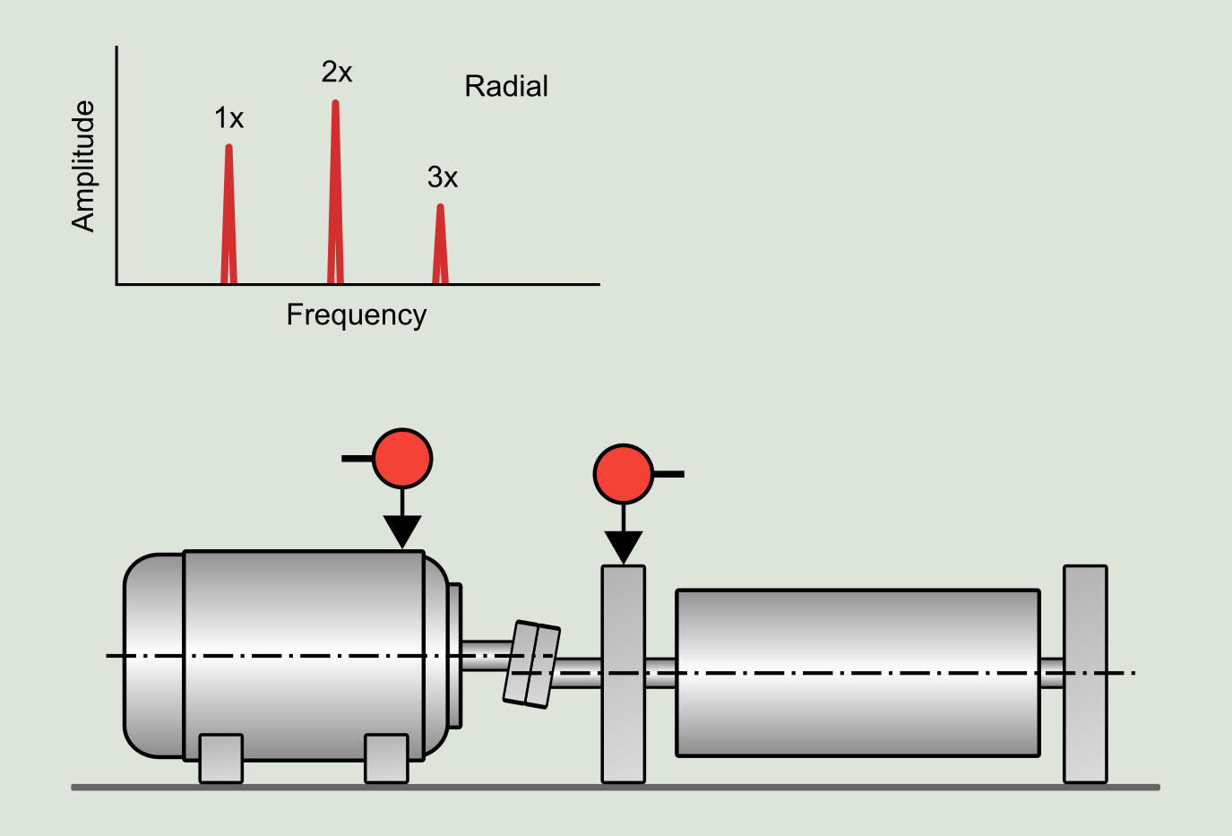
Offset or parallel misalignment
Two shafts suffer parallel misalignment when they are parallel and at a certain distance apart. Misalignment can be vertical or horizontal and manifests in the spectrum with a strong radial vibration at 1x and 2x RPM of the shaft, being able to present higher harmonics of less amplitude.
Symptoms:
- Strong radial vibration in 1x RPM with 2x and 3x harmonics.
- The 2x RPM harmonic in the radial direction can reach a value equal to or even greater than 1x.
- The radial phase measurements on both sides of the coupling are 180° out of phase.
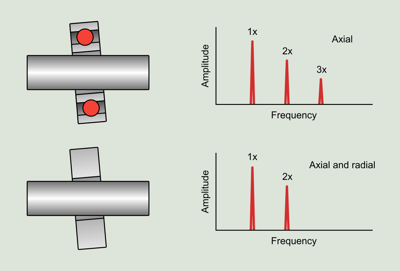
Bearing misalignment
Regardless of whether there is good alignment at the coupling, there may be misalignment between the shaft and the bearing. Misalignment may be caused by a distortion in the machine or improper mounting. If one foot of the machine is not in the same plane as the others or if the base plate is not flat, the tightening of the anchoring bolts will cause a deformation and consequently a misalignment. Another example of bearing misalignment occurs on large fans where the bearing housings are mounted on the metal structure of the fan. If the metal structure does not have sufficient rigidity, it will deform under load conditions and cause misalignment. Generally, the greater deformation is usually produced at the bearing near the impeller, causing axial misalignment.
Misaligned ball or cylindrical roller bearings are characterized by axial vibration regardless of the balancing status. Vibration can appear at 1x, 2x, 3x RPM or at the number of bearing balls or rollers multiplied by the rotating speed.
Anti-friction bearing misalignment produces radial and axial vibration, usually at 1x and 2x RPM of the rotating speed. Bearing misalignment is often accompanied by rotor unbalance, so that a balancing of the rotor will reduce radial and axial vibration.
Symptoms:
- Strong axial vibration at 1x RPM possibly with harmonics at 2x and 3x.
- The 2x RPM harmonic in the axial direction can reach a value equal to or even greater than 1x.
- The axial phase readings at the bottom, left, top and right of the bearing are 90° out of phase.
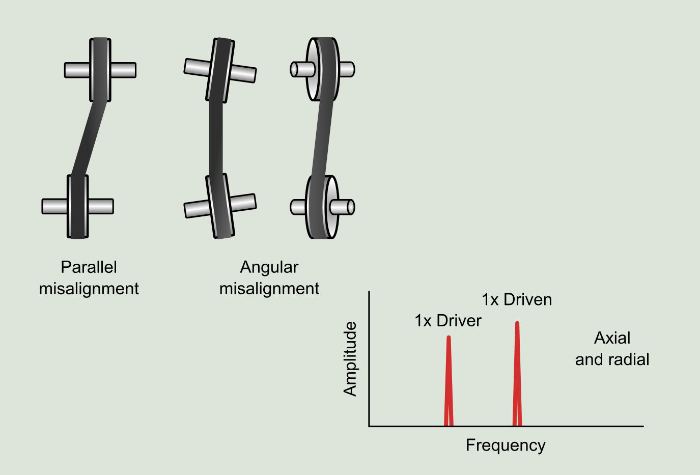
Misaligned pulleys
Two pulleys are considered misaligned when they are not in the same plane. This problem produces high axial vibration at 1x RPM of the driver or the driven system, although generally the driven. A good measurement of the vibration amplitudes is heavily influenced by the location where the data is acquired. The belt pass frequency and its harmonics are also present in the vibration signature. Keep in mind that belt frequencies also tend to appear when there is wear on them, so it is sometimes convenient to check their status. To solve the problem, the pulleys must be aligned both in terms of angle and offset.
Symptoms:
- High axial and radial vibration at 1x RPM of the driver or driven system.
- The vibration is more important in axial than in radial direction (this fact allows to discard unbalance).
- Uneven wear in axial direction on pulleys and belts.